Page 56
Top View
I
G
J
H
A
D
B
E
F
C
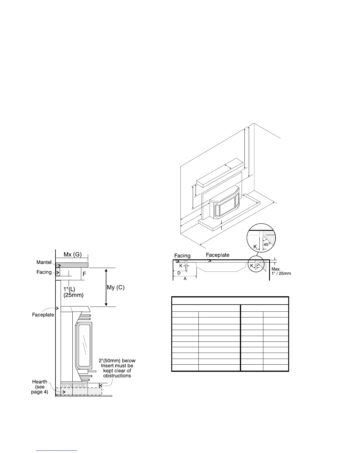
CLEARANCES TO COMBUSTIBLES
The clearances for the Zero Clearance Kit are 0" to combustibles (back, side and floor) but when planning your
installation review the clearances required for the Insert (see below) after it is installed in the Zero Clearance Kit.
The Zero Clearance Kit must be installed on a flat, solid, continuous surface (e.g. wood, metal, concrete). This may
be the floor, or raised up on a platform to enhance its visual impact.
INSTALLATION INSTRUCTIONS
Clearances to Combustibles
for U41/I41 Insert
From Unit
Sides A 9.5" / 241 mm
Drop Ceiling B 35" / 890 mm
Mantel C(My) 12.5 / 320 mm
From Surround
Sides D 2" / 50 mm
Drop Ceiling E 25.5" / 650 mm
Mantel F 3" / 75 mm
Mantel Depth G(Mx) 7.5" / 190 mm
Min. Alcove Width J 48" / 1120 mm
Facing (Mantel Leg)
Side* K 1" / 25 mm
Top L 1" / 25 mm
Combustible Mantel Clearances
Depth (MX) Clearance (MY)
(inches) (mm) (inches) (mm)
*Max. width of 1"(25mm) at 1"(25mm) from surround,
calculate depth at 45
o
as shown in the diagram.
Note: A non-combustible mantel may be installed at a lower
height if the framing is made of metal studs covered with a
non-combustible board.
0" to 5.5" 0mm to 140mm 11" 280mm
6.0” 153mm 11-3/8" 289mm
6.5” 165mm 11-3/4" 299mm
7.0” 178mm 12-1/4" 312mm
7.5” 191mm 12-1/2" 318mm
8.0” 203mm 12-5/8" 321mm
8.5” 216mm 12-3/4" 324mm
9.0” 229mm 12-7/8" 327mm
9.5” 242mm 13" 330mm