15 16
Note:
- Before connecting the probe and test lead at lower
voltage ranges, the display may show erratic readings.
This is normal because the meter is highly sensitive.
Once a connection is made, the true reading will be
displayed.
- “OL” indicated an over-range situation in manual mode.
A higher range should be selected.
- In manual mode, select the highest range first if the
value to be measured is unknown beforehand and
lower as needed.
- Millivolt range (mV) is only available in manual range
mode.
4.9 Resistance
Risk of electric shock. be sure all power to circuit
is off and capacitors have fully discharged before
measureing resistance
WARNING
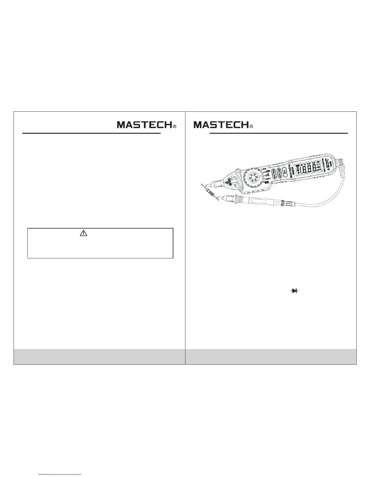
4.9.1 Use the probe cover if making measurements on
category III installations.
4.9.2 Insert the black test lead into the COM jack.
4.9.3 Turn the rotary switch to the Ω position. Press
“RAN” to switch to manual range if needed.
4.9.4 Connect the test probe and test lead across the
resistance for measurement.
4.9.5 The display will show the measured value.
Note:
- “OL” indicated an over-range situation in manual mode.
A higher range should be selected.
- If the resistance measured is greater than 1M , the
meter may take a few seconds to get a stable reading.
This is normal for high resistance measurements.
- When the leads are not connected or when measuring
an open circuit, the display will read “OL”.
Ω
4.10 Diode Test
4.10.1 Use the probe cover if making measurements on
category III installations.
4.10.2 Insert the black test lead into the COM jack.
4.10.3 Turn the rotary switch to the position.
4.10.4 The default mode is resistance.Press “FUNC” to
switch to diode test.
4.10.5 Connect the test probe to the anode (+) and test
lead to the cathode (-) of the diode.
4.10.6 The display will show the measured value