17 18
Note:
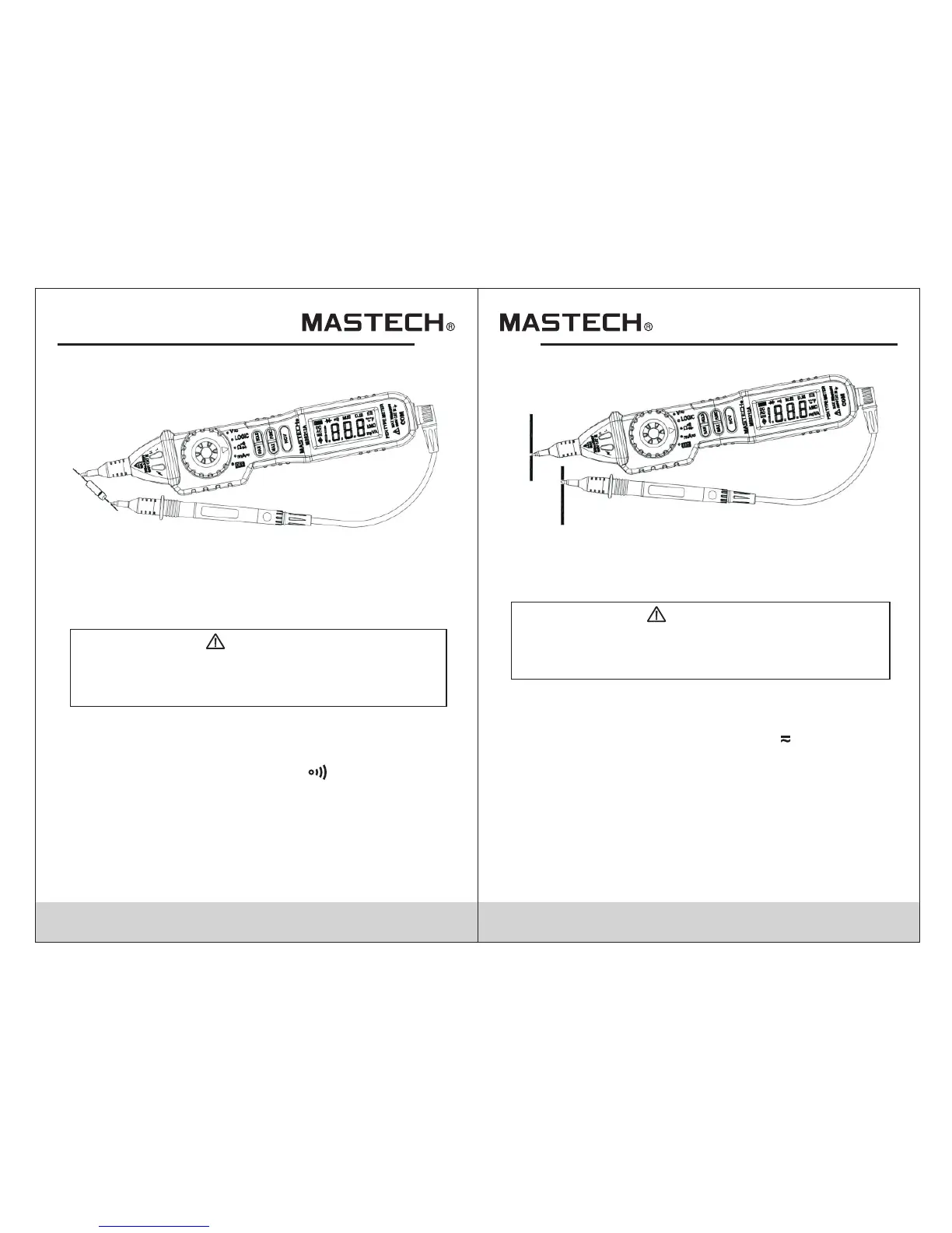
- The display shows the approx. forward voltage drop.
- If the connections are reversed or the leads are not
connected, the display will show “OL”.
4.11 Continuity
Risk of electric shock.be sure all power to circuit
is off and capacitors have fully discharged before
measureing continuity
WARNING
4.11.1 Use the probe cover if making measurements on
category III installations.
4.11.2 Insert the black test lead into the COM jack.
4.11.3 Turn the rotary switch to the position.
4.11.4 The default mode is resistance.Press “FUNC”
twice to switch to continuity.
4.11.5 Connect the test probe and test lead across the
circuit for measurement.
4.11.6 If the measured resistance is less than 50Ω, the
buzzer will sound.
Note:
- If the leads are not connected or the resistance is higher
than 200Ω, the display will show “OL”.
4.12 DC Current
Risk of electric shock.never measure current
where open circuit voltages exceed 250V to
prevent damage to the meter or personal injury.
WARNING
4.12.1 Use the probe cover if making measurements on
category III installations.
4.12.2 Insert the black test lead into the COM jack.
4.12.3 Turn the rotary switch to the“ ” position.
4.12.4 The default mode is DC current.Press “ ” to
switch to manual range if needed.
4.12.5 Connect the test probe and test lead in series
with the circuit under measurement.
4.12.6 The display will show the measured value.
Observe the polarity of the test probe for DC
current measurements.
RAN
mA
Note:
- “
A higher range should be selected.
OL” indicated an over-range situation in manual mode.