05 06
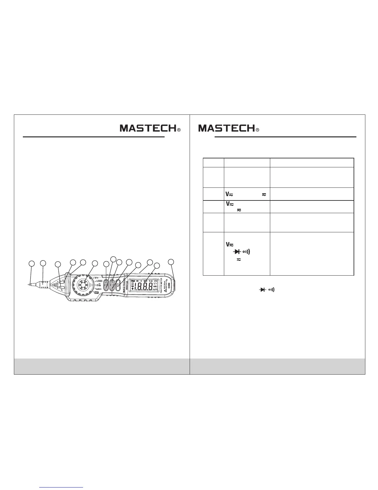
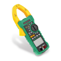
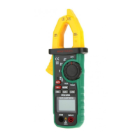
2.1 Front Panel
1.Positive test probe (+)
2.Probe cover (removable)
3.NCV Indicator
4.LED indicators
5.Protective ring
6.Rotary switch
7.Data hold button (HOLD)
8.Range button (RAN)
9.Function button (FUNC)
10.Max hold button (MAX)
11.Non-contact voltage button (NCV)
12.Panel
13.LCD screen
14.COM jack (-)
2.2 Buttons and Functions
- Function Buttons
mA
Ω
Logic
Switches between DC and AC
voltage.Keep pressing during
the Logic testing. Switches
between Resistance
measurement, Diode Test and
Continuity check.Switches
between DC and AC current.
Button
Function
Description
HOLD
RAN
MAX
Any switch
position
Power-up Option
Ω and mA
This Button is used to hold data.
Disables automatic power-off
feature.
Switch ranges in manual-range.
Hold to return to auto-range.
Used to measure and hold the
maximum value.
NCV
Any switch
position
Power-up Option
Hold for Non-contact voltage
detection.
FUNC
Rotary switch: select between functions.
- Test probe: for V/Ω/ / measurements.
- COM jack: common test lead input.
- LCD display: shows results of measurements.
- LED indicator: In Logic mode, green indicated low
level, red indicated high level.
- Probe cover: used when making category III or higher
measurements.Twist to remove if making category II or
lower measurements.
- Protection ring: Keep hands behind the protection ring
and away from the probe to avoid injury.
- NCV Indicator:Detection of NCV,AC voltage indication.
1
2
4
5
6
7
8
9
10
11
12
14
3
13
Logic
mA