EasyManua.ls Logo

MasterCraft 052-1899-2 User Manual

MasterCraft 052-1899-2
72 pages
To Next Page IconTo Next Page
Page #1 background imageLoading...
Page #1 background image
MULTIMETER
INSTRUCTION
MANUAL
Read and understand this instruction manual thoroughly
before using the product. It contains important
information for your safety as well as operating and
maintenance advice.
Keep this instruction manual for future use. Should this
product be passed on to a third party, then this
instruction manual must be included.
model no. 052-1899-2
Question and Answer IconNeed help?

Do you have a question about the MasterCraft 052-1899-2 and is the answer not in the manual?

MasterCraft 052-1899-2 Specifications

General IconGeneral
ContinuityYes
Diode TestYes
AC Voltage600V
DC Voltage600V
AC Current10A
DC Current10A

Summary

General Description

Safety Information

Warning

Guidelines to avoid electric shock or personal injury when using the multimeter.

Warning

Additional safety guidelines for operating the multimeter safely and correctly.

Warning

Explains how to use the meter safely and warns against certain measurement categories.

Caution

Caution

Guidelines to prevent damage to the meter or equipment under test.

Electrical Symbols

Multimeter Description

1. Display

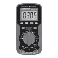
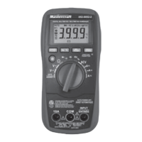
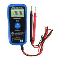
Details the 3 3/4-digit LCD with a max reading of 3999.

2. "RANGE" Button

Explains the function of the RANGE button for auto/manual range selection.

3. "FUNC" Button

Describes the FUNC button for switching between DC/AC, diode/continuity functions.

4. "HOLD" Button

Explains the HOLD button for freezing the display reading.

5. Function / Range Switch

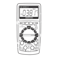
Details the main rotary switch for function selection and power control.

6. "10A" Jack

Identifies the jack for 10A current measurements.

7. "mA°C" Jack

Identifies the jack for mA current and temperature measurements.

8. "COM" Jack

Identifies the common jack for all measurements and thermocouple.

9. "VOHz#" Jack

Identifies the jack for voltage, resistance, and frequency measurements.

10. Backlight Button

Explains the backlight button.

11. "REL" Button

Explains the REL button for Relative Mode.

12. "Hz%" Button

Explains the Hz% button for frequency and duty cycle.

13. Holster

Mentions the holster.

Sensor Instruction

LCD Display

LCD Display Units

General Specifications

Accuracy Specifications

DC Voltage Specifications

AC Voltage Specifications

DC Current Specifications

AC Current Specifications

Resistance Specifications

Frequency Specifications

Capacitance Specifications

Temperature Specifications

Duty Cycle Specifications

Humidity Specifications

Sound Level Specifications

Illumination Specifications

Diode and Continuity Tests

Operating Instructions

Using Relative Mode

Explains how to use the Relative Mode for measurements.

Data Hold Mode

Describes how to activate and deactivate Data Hold mode.

Manual Ranging and Autoranging

Explains the autorange and manual range selection modes.

Built-in Buzzer

Details the conditions under which the built-in buzzer sounds.

Measuring DC or AC Voltage

Measuring DC or AC Current

Measuring DC or AC Current (Continued)

Measuring Resistance

Continuity Test

Measuring Capacitance

Measuring Frequency and Duty Cycle

Diode Test

Measuring Temperature

Measuring Relative Humidity

Measuring Sound Level

Measuring Intensity of Illumination

Auto Power Off

Maintenance

Warning

Warning about repair and storage.

General Maintenance

Instructions for general cleaning and terminal maintenance.

Replacing the Battery and Fuse

Accessories

Warranty Information

Disposal Information

Related product manuals