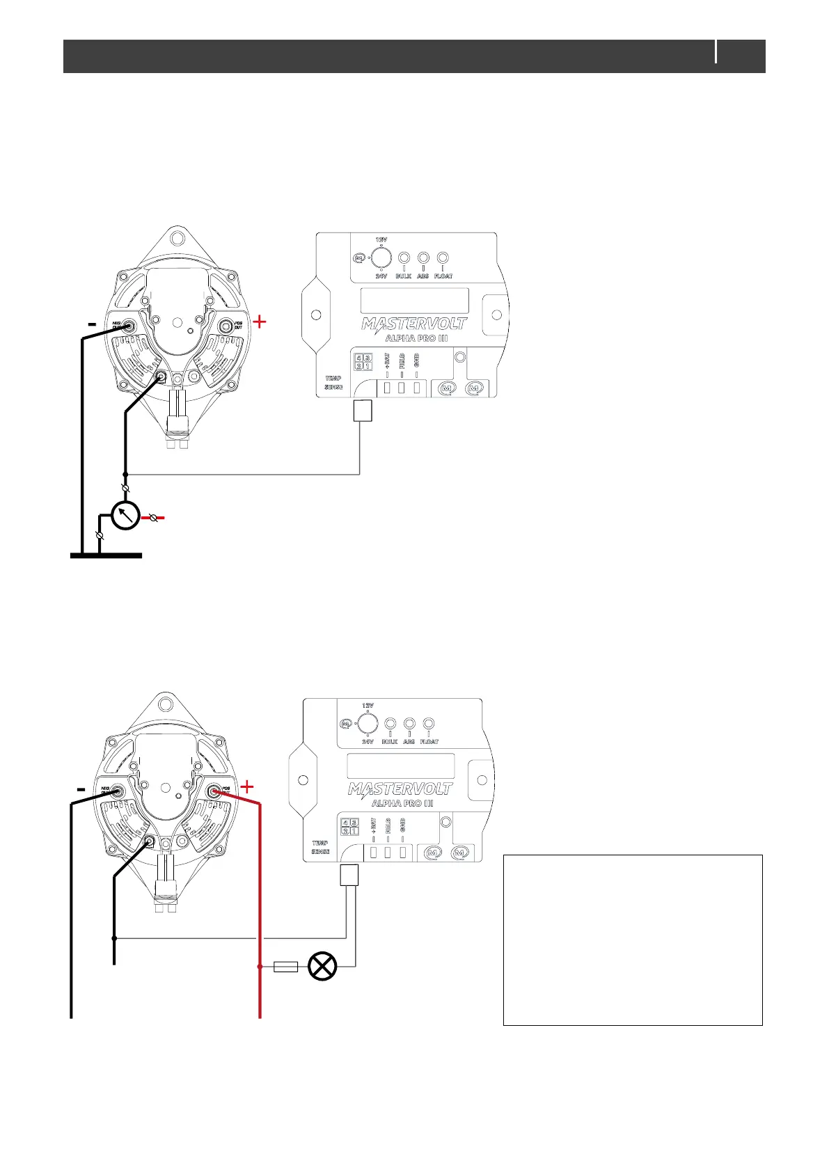
4.2.4 Connection of a tachometer (optional)
If a tachometer is used, it should be connected between the W terminal of the alternator and the B– terminal of the
alternator (or the negative battery pole). See Figure 10.
The Alpha Pro charge regulator has the same function integrated in its MasterBus functionality, so the number of
revolutions per minute (revs or RPM) can be shown on a MasterBus connected display too. To enable this, connect
the white wire from the cable loom to the alternator, and set the number of pole pairs in MasterAdjust.
Figure 10: Connection of a tachometer
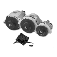
4.2.5 Connection of a D+ lamp (optional)
A standard alternator and engine have a charge indicator lamp. This lamp will go off when the alternator is charging.
The Alpha Pro charge regulator offers the same function. To enable this, connect the yellow and white wires from
the cable loom to the alternator, and select the RPM option in MasterAdjust.
Figure 11: Connection of a D+ lamp
(see the Alpha Alternator Installation Manual for detailed installation drawings)