Alpha Pro charge regulator – User and Installation Manual
3 PRODUCT DESCRIPTION
This user manual describes the installation and operation of the Alpha Pro charge regulator. Together with the
Mastervolt alternators, this charging regulator is designed to provide a high output power at low RPM, which is
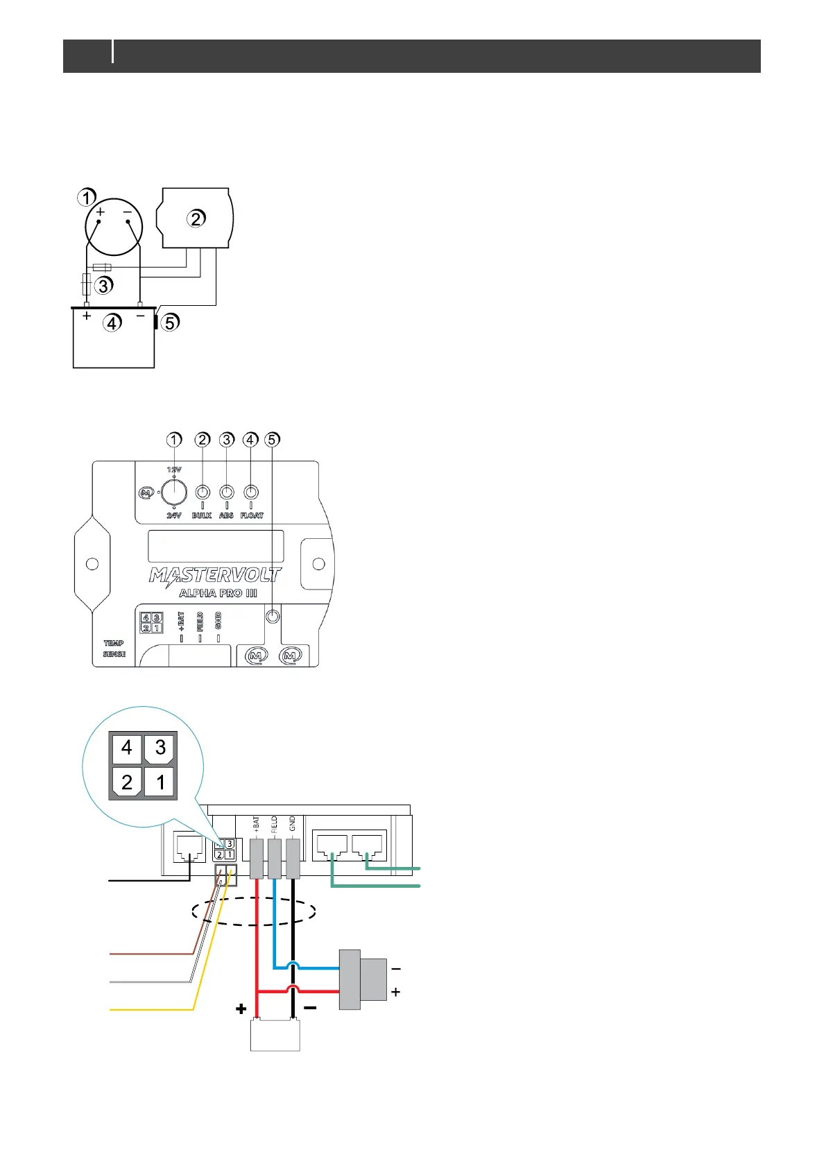
typical for marine applications. It consists of the following main components (See Figure 2):
1 Mastervolt alternator
2 Alpha Pro charge regulator
3 Battery fuses
4 Batteries (not included)
5 Battery temperature sensor
Figure 2: Basic charging system consisting of an alternator and the Alpha Pro charge regulator
3.1 OVERVIEW OF THE ALPHA PRO CHARGE REGULATOR
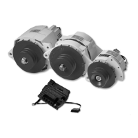
Figure 3: Overview of the Alpha Pro charge regulator (front view)
Figure 4: Connections of the Alpha Pro charge regulator (bottom view)
1 Charging mode selector switch
2 Yellow LED to indicate Bulk phase
3 Yellow LED to indicate Absorption phase
4 Yellow LED to indicate Float phase
5 Green LED to indicate MasterBus traffic
4. Brown – Reg on (excitation/field wire and voltage measurement)
3. Yellow – D+ (warning lamp)
2. White – W (RPM measurement)
1. not used
MasterBus connection (2x)