12/75-3, 12/100-3, 24/40-3, 24/60-3 – User and Installation Manual
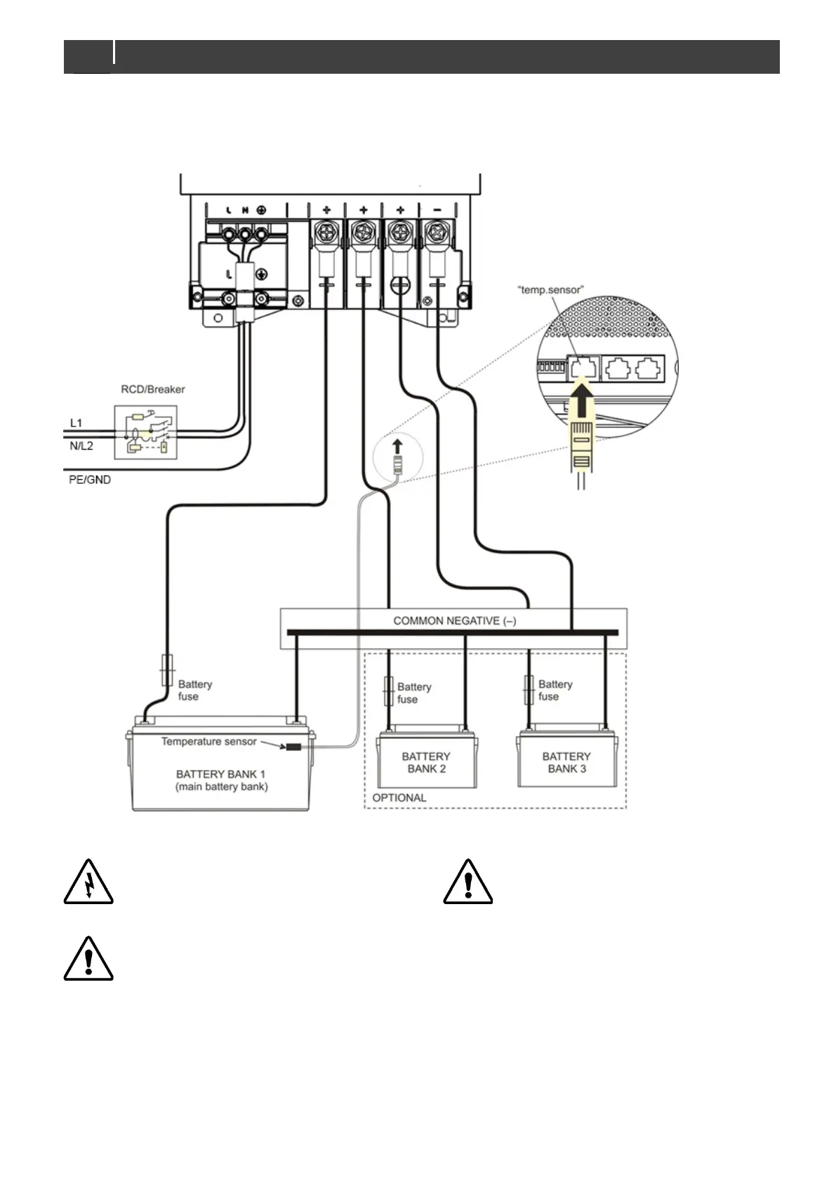
3.7 Connection example
This schematic illustrates the general placement of the ChargeMaster Plus in a circuit. It is not meant to provide detailed wiring
instructions for any particular electrical installation.
Figure 3: Installation drawing of the ChargeMaster Plus
All electrical systems (AC and DC) must be
disconnected from any power source during
the entire installation!
Too-thin cables and/or loose connections can
cause dangerous overheating of the cables
and/or terminals. Therefore,
connections well, in
order to limit transition
resistance as far as possible. Use cables of
Short circuiting or reversing polarity may lead
to serious damage to the batteries, the
ChargeMaster Plus, the cabling and/or the
terminal
connections. Fuses between the
batteries and the ChargeMaster Plus cannot
prevent damage caused by reversed polarity.
The damage as a result of reverse polarity is
detectable by the service department and is
not covered by the warranty.