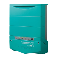
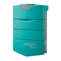
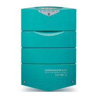
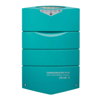
ChargeMaster Plus 12/75-3, 12/100-3, 24/40-3, 24/60-3 –
User and Installation Manual
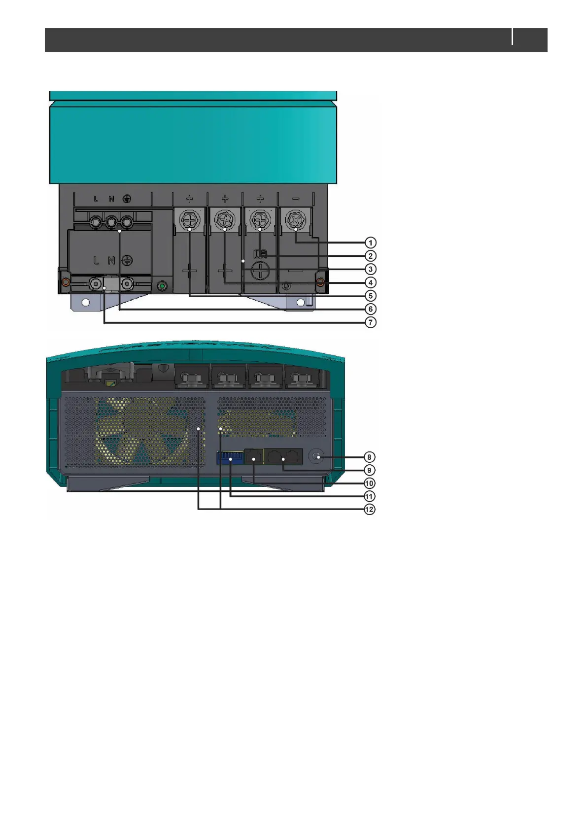
3.6 Overview connection compartment
1 Common negative output terminal 7 Cable clip for AC wiring
2 Positive terminal charge Smart terminal 8 Safety ground connection
3 Isolation walls for DC connections 9 MasterBus connection
4 Positive terminal charge output 2 10 Temperature sensor connection
5 Positive terminal charge output 1 11 DIP switches
6 Screw terminals AC input 12 Ventilation openings
Figure 2: Connection compartment
Notes:
˗ If the battery temperature remains within 15-25°C, connection of the battery temperature sensor is optional.
˗ The ChargeMaster Plus is only feasible for the connection of MasterBus compatible remote control panels.
˗ When creating a parallel system of multiple ChargeMaster Plus units, the units should be excluded from any isolation
measurement system.