CombiMaster 120V Series – User and Installation Manual
5 SETTINGS
Adjustment of the settings of the CombiMaster Inverter/Charger can be made in two different ways:
• By means of DIP switches.
• From a laptop connected to the CombiMaster Inverter/Charger via a USB Interface. Some settings,
like the AC IN Limit setting for example, can only be changed in this way.
CAUTION!
Invalid settings of the CombiMaster Inverter/Charger can cause serious damage to your
batteries and/or the connected load! Adjustment of settings must be carried out by authorized
personnel only.
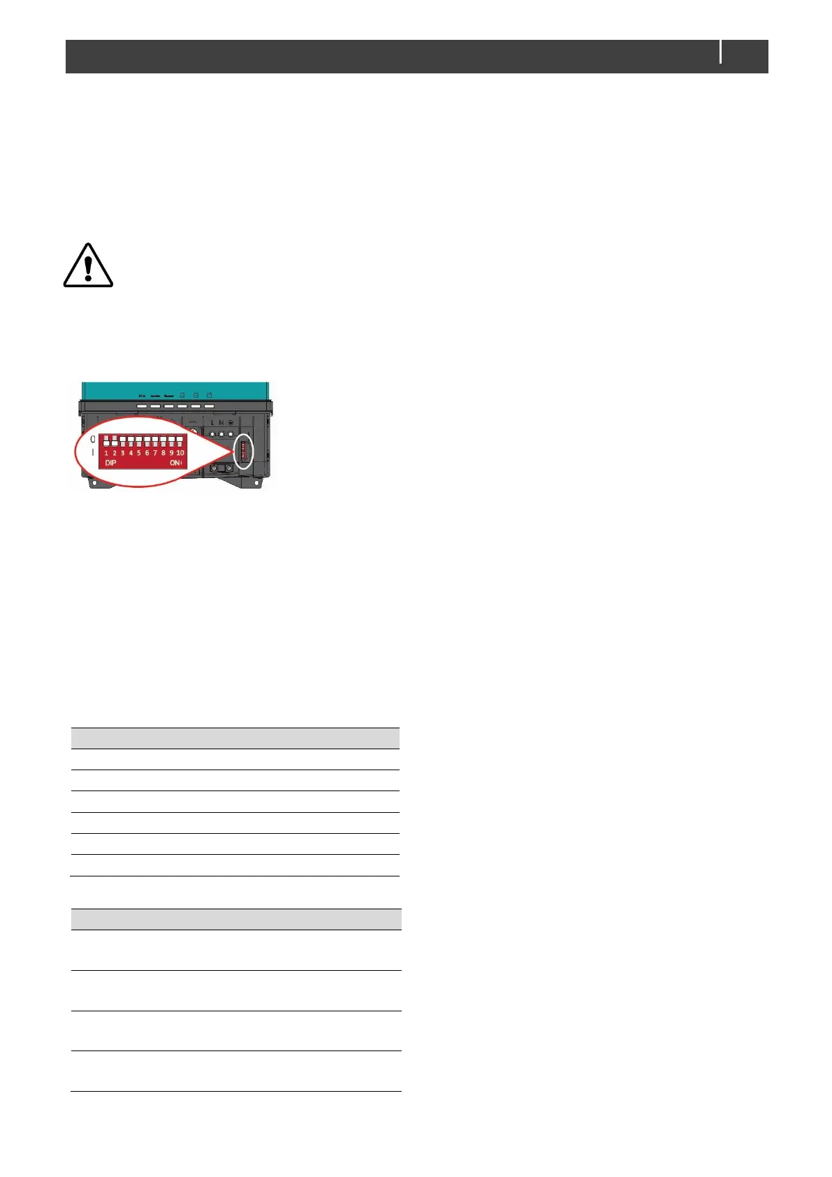
5.1 DIP switch settings
Use a small screwdriver to carefully set the required settings.
DIP switch 1 = CZone network (0) or MasterBus network (1).
DIP switch 2 = MasterBus powering off (0) or on (1)
DIP switches 3 to 10 are either used as CZone address or for
MasterBus battery and 3
rd
output settings.
Figure 4. DIP switches (factory settings)
In a CZone network:
DIP switch 1 must always be set to the OFF position (0 ).
DIP switch 2 must always be set to the OFF position (0 ).
DIP switches 3 to 10 must match the unique address used in the CZone network; the dipswitch (see the
CZone Configuration Tool Instructions manual).
In a MasterBus network:
DIP switch 1 must always be set to the ON position (1 ).
DIP switch 2 is MasterBus Powering ON (1 ) or OFF (0 ). By default, this is OFF.
DIP switches 3 to 5 are used for battery type selection:
MasterBus settings (Flooded)
1
Constant voltage (13,25V)
2
The following table lists the settings for DIP switches 6 to 9.
Inverter frequency 60Hz
Inverter frequency 50Hz
AC input support mode off
AC input support mode on
AC voltage input window wide
AC voltage input window narrow
Energy saving mode off
Energy saving mode on
1
If all DIP switches are in the OFF position
(0 ), the settings suit a Flooded battery
but can be changed in MasterAdjust.
2
Constant voltage has no temperature
compensation.