66
10.4 TV BRACKET INSTALLATION INSTRUCTIONS - CONTINUED
CHAPTER 10: TREADMILL SPECIFICATIONS AND ASSEMBLY GUIDE
FIGURE G FIGURE H
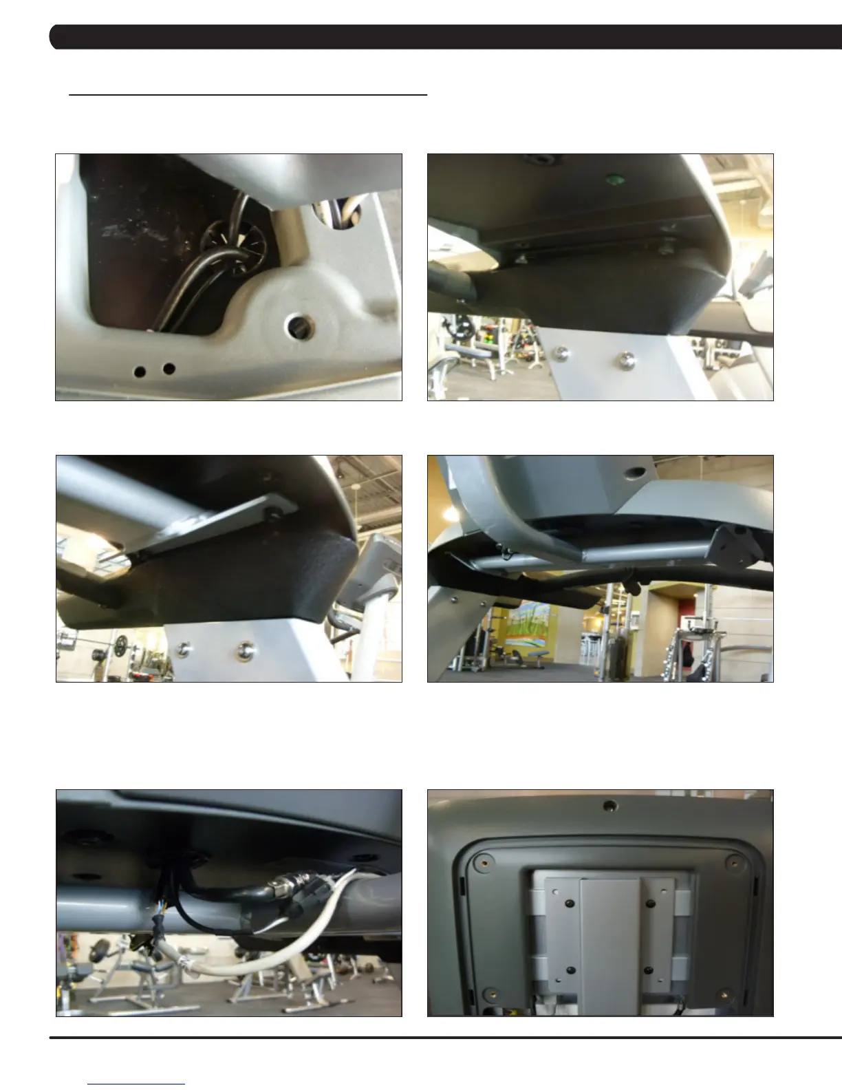
9. Feed the coax cable and TV power wire (4 pins - both wires come up the console mast), and controller signal wire (8 pins - from the console)
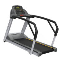
through the hole in the handlebar frame below the console (Figure G).
10. Remove the 4 screws holding the upper handlebar assembly to the console masts (Figure H).
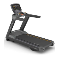
11. Mount the TV bracket to the frame using the 4 screws removed in Step 4 (Figures I & J).
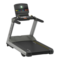
12. Connect the coax cable, TV power wire, and controller signal wire that you fed through the hole in the handlebar frame in Step 9 to the
cables coming out of the TV bracket (Figure K). NOTE: There is a wire in the TV bracket that is not currently used (it has a 6 pin connector on
one end and a yellow RJ45 connector on the TV end of the bracket).
13. Re-install the console onto the handlebar frame.
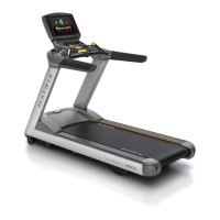
14. Install the TV to the TV bracket using 4 screws sent with the TV (Figure L).
FIGURE LFIGURE K
FIGURE JFIGURE I
 Loading...