32
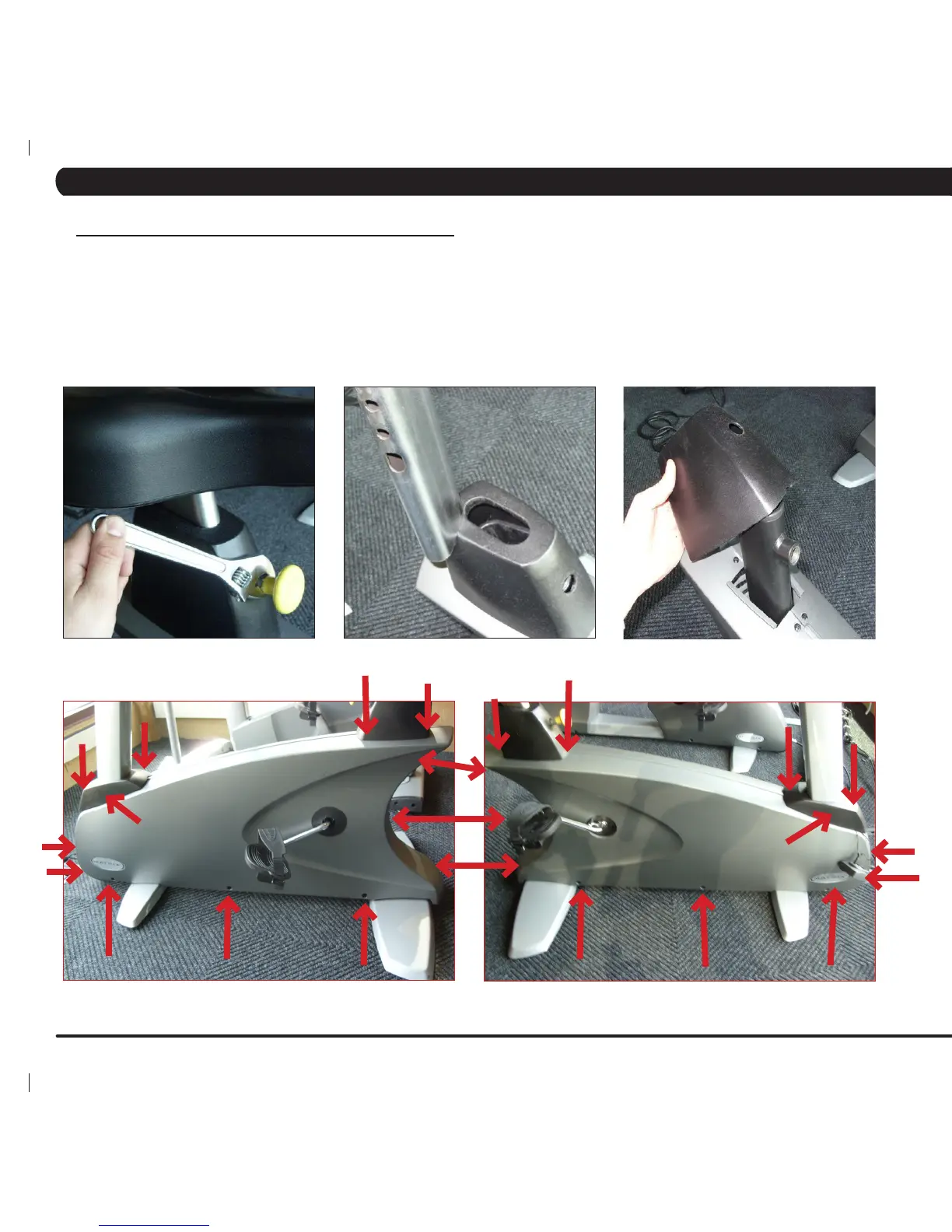
8.11 SHROUDS REMOVAL
1) Remove the pedals as outlined in Section 8.10.
2) Remove the seat adjustment pin (Figure A).
3) Remove the seat post and seat post boot (Figures B & C).
4) Remove the 13 screws holding the left shroud in place (Figure D).
5) Remove the 13 screws holding the right shroud in place (Figure E).
6) Once the screws are removed from both side shrouds, lift the shrouds away from the frame. NOTE: You will need to angle the shroud so
that the crank passes through the hole in the shroud.
CHAPTER 8: PART REPLACEMENT GUIDE
FIGURE A
FIGURE B
FIGURE C
FIGURE D FIGURE E