CD 30 ÷ 520
33
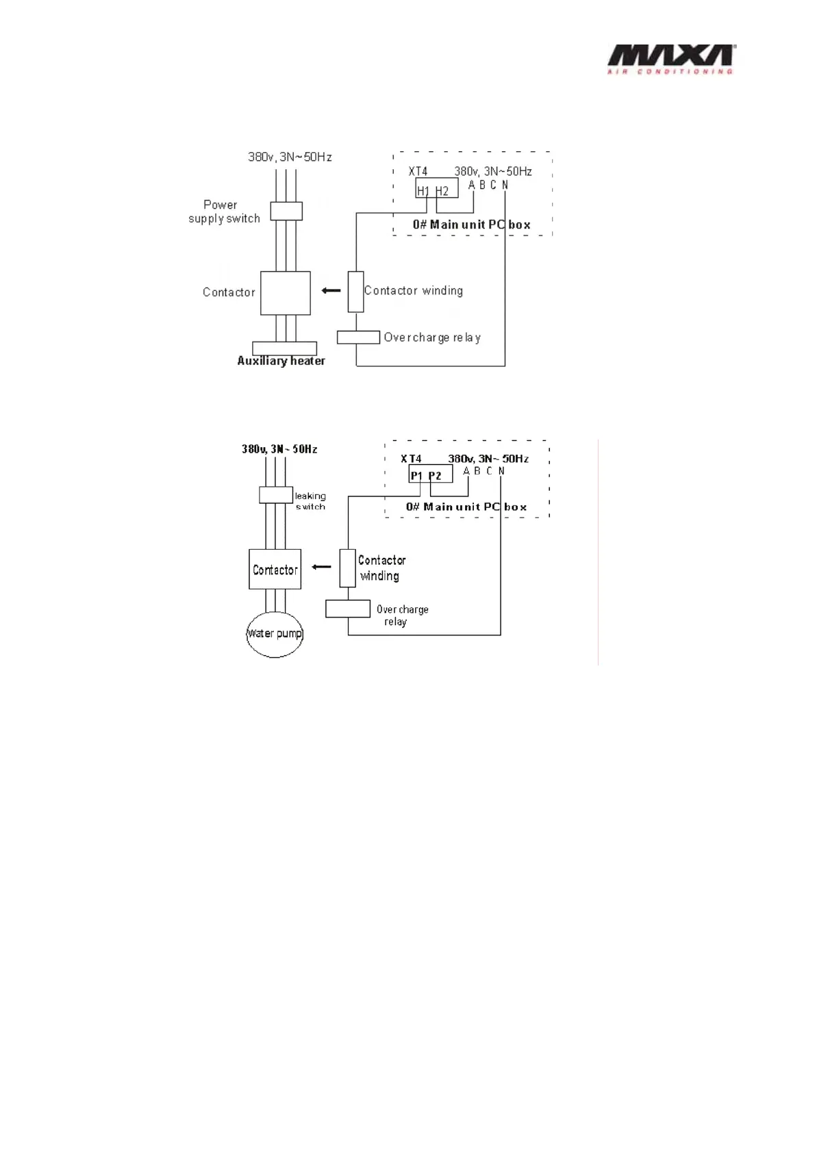
Auxiliary electric heater control wire connection: the control wire of AC contactor must pass the
main unit’s H1, H2 terminals as below:
Water pump control wire connection: the control wire of AC contactor must pass P1ǃP2
terminals of main unit as below:
Notice: Water flow switch, water pump and auxiliary electric heater can just be connected to the
main unit controller which is set as 0 addresses.
12. Debugging
Preparation
After cleaning the water system pipeline for several times, ensure the water is clean, then
pump and drain again, and start the pump to ensure the flow and the pressure of inlet and outlet
pipeline is qualified.
Notice: the water pump is under the control of the main unit, so when the water system is
running, it can make the control circuit of water pump AC contactor electrify by temporarily
wiring, thus to make the water pump running.
Warning: it is absolutely forbidden to start the pump by the control of main unit before the water
system has been adjusted well.
Please set the address switch on the unit controller according to the rule below.