CD 30 ÷ 520
30
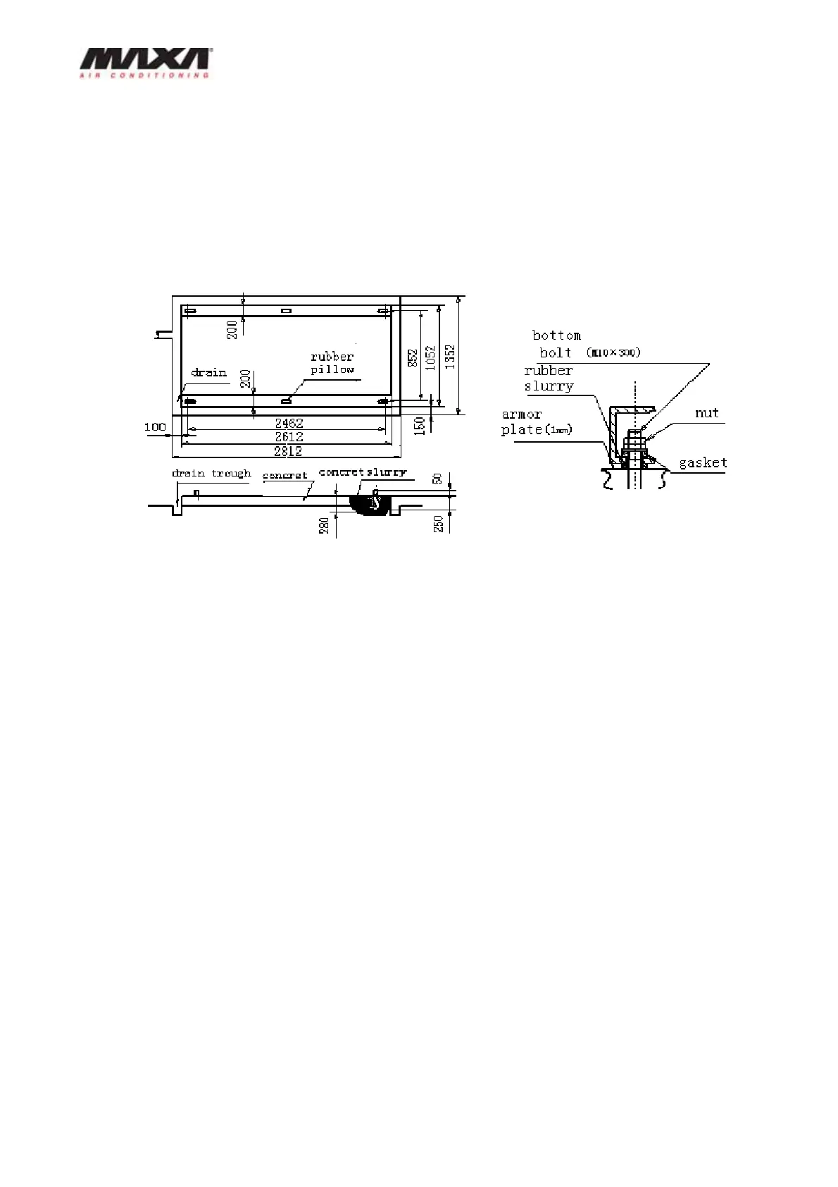
Installation reference
The installation basement for main module is shown as follows; the auxiliary module is the
same as the main one. 60mm distance should be left between modules. The weight that the
concrete can support should be 1.5 to 2 times of the weight of modules when the modules are
installed on the ground.
11. Water system installation
Every pipeline’s joint has marks of water-outlet and water-inlet mark. The following should be
noticed when connecting pipelines:
The water passage is narrow due to the adoption of plate heat exchanger, so it is easily
jammed by particles or dust, which may cause freezing and damage the system. To prevent this
problems, the users should try to install a Y shape filter with 20 item reticulation at the inlet of
chilled-water or cooled-water near the module.
The water pipeline should be cleaned before connecting to the unit, then dismantle the filter and
install again. After confirming the water pipeline is clean, the connection can be done.
The soft connector should be used at the inlet (outlet) water pipe to avoid vibration.
To ensure turn on the water pump first and then the unit, the water switch should be installed on
the inlet pipeline and connect its wire to terminal W1 and W2 of main unit.
Water discharge switch should be installed at the outlet pipe, and gas discharge valve should
be installed at the inlet water pipe. When the unit works normally, the handler of valve must be
taken away to ensure the valve can’t be opened. If the water discharge valve is opened when
the unit is running, water breaking-off will occur.
The freeze-water pipeline should be covered with adequate heat-insulating material to keep the
chilled-water temp. and prevent dewing.