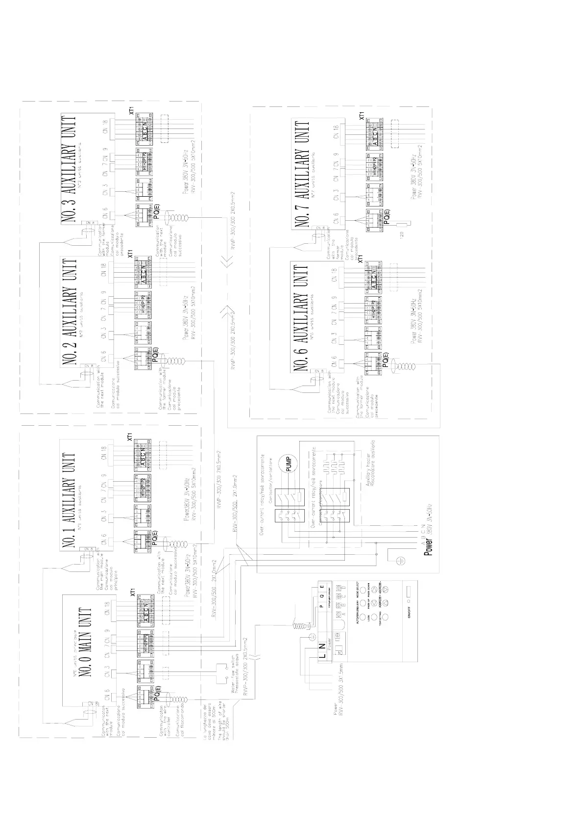
18. Unit electric control & communication figure for 65KW unit
O
Black
Yellow
Gray
Note: The wiring diagram of auxiliary heater is just
for reference,please follow the instructions of
corresponding auxiliary heater products. Please
choose such accessory as power wire, switch of
water pump and auxiliary heater according to the
actual
arameter of
roducts and national standards
The wiring terminal P,Q,and E on the back of
Wire Controller are corresponding to the
Terminal P,Q, and E of Wiring Board in Main
Module
The metal plate of contactor installation box
should be grounded