Setup
Installation
EPOS4 EtherCAT Card Hardware Reference
CCMC | 2019-11 | rel8613
3-13
3.3 Installation
The procedure varies depending on the type of controller you are using:
• EPOS4 controllers with encased housing feature two ready-to-use extension slots.
• EPOS4 Modules require a custom-made motherboard (for details on design and layout chapter
“4 Motherboard Design Guide” on page 4-17) with a PCIe card edge connector.
Hot plugging/hot swapping the card may cause hardware damage
Switch off the controller’s power supply before removing or inserting an extension card.
Electrostatic sensitive device (ESD)
• Wear working cloth and use equipment in compliance with ESD protective measures.
• Handle device with extra care.
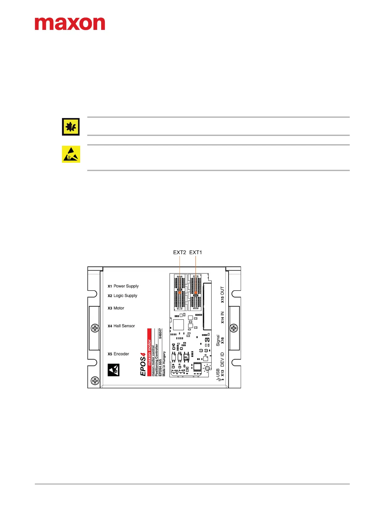
3.3.1 EPOS4 Controllers with encased Housing
The controllers provide two extension slots (EXT1 & EXT2) located underneath the plastic lid at the hous-
ing’s top face (Figure 3-4). The plastic lid will mechanically interlock the inserted extension card in both
horizontal and vertical direction.
• EXT1 hosts the «EPOS4 EtherCAT Card».
• EXT2 provides connectivity for advanced signal extension cards, such as for additional absolute
sensors or customized signal extensions.
Figure 3-4 Extension slots – as an example «EPOS4 50/5»
Continued on next page.
 Loading...