Do you have a question about the Maytag CWG3600AAS13 and is the answer not in the manual?
This document provides comprehensive installation instructions for a 24" (61.0 cm) gas single and double built-in oven, emphasizing safety, proper setup, and gas conversion procedures. It is designed for both qualified installers and homeowners, with clear guidance on each step of the installation process.
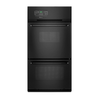
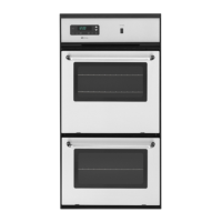
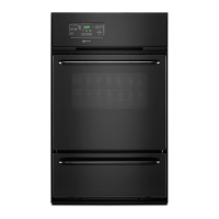
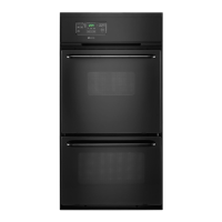
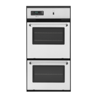
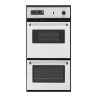
The primary function of this appliance is to provide a gas-fueled oven for baking and broiling within a kitchen setting. It is available in both single and double oven configurations, offering flexibility to suit various kitchen layouts and cooking needs. The oven utilizes an electric control system and an electric oven burner igniter for operation, ensuring efficient and reliable ignition of the gas.
Safety is paramount throughout the installation and operation of the oven. The manual prominently features a "BUILT-IN OVEN SAFETY" section, which uses safety alert symbols and keywords like "DANGER" and "WARNING" to highlight potential hazards. These messages cover critical aspects such as fire and explosion risks associated with gas leaks, proper handling of flammable materials, and the importance of professional installation and service.
The document stresses that gas leaks cannot always be detected by smell and recommends the use of a UL or CSA approved gas detector. In the event of a gas smell, specific instructions are provided: do not try to light any appliance, do not touch any electrical switch, do not use any phone in the building, and immediately call the gas supplier or fire department.
For installation, the manual requires the use of a new CSA International approved gas supply line and a shut-off valve. All gas connections must be securely tightened. If connected to LP gas, a qualified person must ensure that gas pressure does not exceed 14" (36 cm) water column. Examples of qualified personnel include licensed heating personnel, authorized gas company personnel, and authorized service personnel. Failure to follow these instructions can result in death, explosion, or fire.
Electrical safety is also emphasized, with a "WARNING Electrical Shock Hazard" section. Users are instructed to plug the oven into a grounded 3-prong outlet, not to remove the ground prong, and to avoid using adapters or extension cords. The oven must be electrically grounded in accordance with local codes and ordinances, or with the National Electrical Code, ANSI/NFPA 70 or Canadian Electrical Code, CSA C22.1. A 120-volt, 60 Hz, AC only, 15-amp fused electrical circuit is required, with a time-delay fuse or circuit breaker recommended. It is also recommended that a separate circuit serve only the oven.
The "INSTALLATION REQUIREMENTS" section details the necessary tools and parts, location requirements, electrical requirements, and gas supply requirements.
Installers must observe all governing codes and ordinances and ensure that the flow of combustion and ventilation air is not obstructed. The oven should be conveniently located in the kitchen, and the recessed installation area must provide complete enclosure around the recessed portion of the oven. All openings in the wall or floor where the oven is to be installed must be sealed. Specific cabinet opening dimensions are provided to ensure proper clearance. The appliance is designed to comply with maximum allowable wood cabinet temperatures of 194°F (90°C).
A 120-volt, 60 Hz, AC only, 15-amp fused electrical circuit is required. The outlet must provide 120-volt power and be correctly grounded for the electronic ignition system. The wiring diagram is located in the upper control compartment in a clear plastic bag.
A gas supply line of 3/4" (1.9 cm) rigid pipe is required to the oven location. For LP gas, piping or tubing size can be 1/2" (1.3 cm) minimum. Pipe-joint compounds resistant to LP gas must be used, and TEFLON® tape should not be used. If local codes permit, a new CSA design-certified flexible metal appliance connector (4 to 5 ft long, 1/2" or 3/4" I.D.) may be used. A 1/2" (1.3 cm) male pipe thread is needed for connection to the appliance pressure regulator. A manual shutoff valve must be installed in the supply line, located in the same room but external to the oven, allowing ease of opening and closing.
The installation process begins with preparing the built-in oven. This involves disconnecting power, deciding on the final location, setting the oven onto cardboard to prevent floor damage, removing shipping materials, hardware, racks, and other parts. The oven door must be removed by opening it to the broil stop position (about 4" to 6"), grasping the sides at the middle, and lifting it straight up while slightly opening it to allow latches to swing down into hinge arm notches.
This critical step involves applying pipe-joint compound to the smaller thread ends of the flexible connector adapters, attaching one adapter to the gas pressure regulator and the other to the gas shutoff valve, and tightening both. A 15/16" combination wrench and an adjustable wrench are used to attach the flexible connector to the adapters, ensuring it is not kinked. The gas supply pipe must be located within the specified clearance area.
The manual shutoff valve in the gas supply line is opened (handle parallel to the gas pipe). All connections are then tested by brushing on an approved noncorrosive leak-detection solution; any bubbles indicate a leak that must be corrected.
With two or more people, the oven is lifted partially into the cabinet cutout, using the oven opening as a grip area. The oven is pushed completely into the cabinet, centering it within the cutout, pushing against the seal area of the oven front frame, not the outside edges. The oven is then securely fastened to the cabinet using provided screws (4 for single, 6 for double oven) through holes in the decorative trim. Pilot holes should be pre-drilled using a 0.140" diameter (number 28) drill bit to prevent cabinet damage, and screws should not be overtightened.
Oven racks are replaced, and the oven door(s) are reinstalled by aligning slots with hinge arms, sliding the door down, and gently pushing it downward until it rests evenly on the hinges. Power is reconnected, and the display panel should light up briefly, showing "PF." If the display does not light, troubleshooting or contacting the dealer is advised.
The oven's electric control system and igniter require no adjustment. When the oven control is turned on, a glow bar igniter heats and ignites the gas.
Power is turned on, the time should flash, and the oven door(s) should be closed. The oven(s) Broil function is turned on. After 5 minutes, heat should be felt. If no heat is felt or an "F" followed by a number appears, the oven should be turned off, and a qualified technician contacted. Finally, CANCEL is pressed.
The BAKE function is pressed, and "BAKE" and temperatures will show. The igniter will glow, and the oven bake burner should light within 60 seconds. If burners do not light properly, CANCEL is pressed, and checks are made for power connection, tripped circuit breakers, and open gas shutoff valves. If the burner still does not light, the dealer or authorized service company should be contacted.
The manual provides detailed instructions for converting the oven from Natural gas to LP gas or from LP gas to Natural gas. This conversion must be performed by a qualified installer.
The document implicitly covers maintenance through its emphasis on proper installation and initial checks. By ensuring correct gas connections, electrical grounding, and burner operation during installation, the likelihood of future issues is reduced. The "Check Operation of Oven(s)" and "Check Operation of Bake/Broil Burner" sections serve as initial maintenance checks to confirm the appliance is functioning correctly after installation. If issues arise, such as no heat or error codes, the user is directed to consult the "Assistance or Service" section of the Use and Care Guide or contact the dealer. The manual also advises homeowners to keep the installation instructions for future reference, which is a key aspect of long-term maintenance and troubleshooting. The wiring diagram, located in a clear plastic bag in the upper control compartment, is a valuable resource for service technicians.
| Brand | Maytag |
|---|---|
| Model Number | CWG3600AAS13 |
| Color | Stainless Steel |
| Fuel Type | Gas |
| Oven Capacity | 5.0 cu. ft. |
| Oven Cooking Modes | Bake, Broil |
| Self-Cleaning | Yes |
| Warranty | 1 Year Limited |
| Width | 30 inches |
| Burner Type | Sealed |