3
PREPARATION
Before proceeding with installation of iQ air conditioning
equipment, consult with the distributor and homeowner to
confirm that the equipment listed on the order is what was
ordered, and that it matches labeling on the equipment
packaging.
Determine (including consultation with the homeowner) the
intended/preferred location for placement of the compressor/
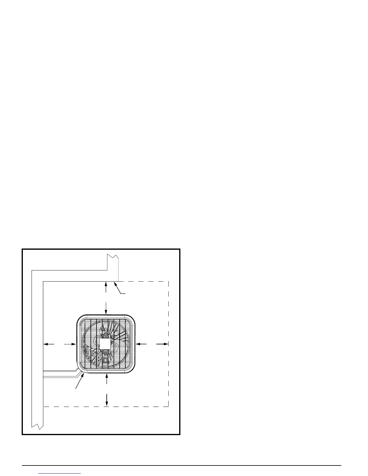
outdoor coil unit. Unit envelope dimensions are shown in
Figure1.
This air conditioner is designed for outdoor installation only.
Unit placement must take into consideration the following
clearances:
• Aminimumof12inchesmustbeprovidedbetweeneach
of the four sides and any solid barrier or wall which might
blockfreeinletairowintothecoil.Aminimumclearance
of 18 inches is required between multiple units.
• Thecorneroftheunitcoveredbythecontrolaccesscover
must be clear enough to allow comfortable access by a
serviceperson.
• Thetopoftheunitmustbeopenandunobstructedtoprevent
recirculation of outdoor fan discharge air, particularly for air
conditioning usage. A minimum distance of 4 feet overhead
clearance is recommended. Do not locate the unit in a pit
with high walls on all sides.
Locatetheunitawayfromoverhangswhichwouldallowwater
runoff or ice to fall directly onto the air conditioner. In low
temperature climates, place the unit where it is not directly
in prevailing winds. Avoid placing the air conditioner near
sleeping quarters or windows.
Slab Mounting
• Thepreferredunitmountingisonanoutdoorslab(concrete
or plastic), on the ground, in an area with good drainage
unlikelytobeaffectedbyheavyrunoff,groundsettling,or
deep snowdrift accumulation.
• Thesupportslabshouldbelevel.Makesurethatthedrain
holes in the bottom of the unit are not obstructed.
Roof Mounting
The method used for roof mounting should be designed so
as not to overload roof structures nor transmit noise to the
interior of the structure. Refrigerant and electrical lines should
be routed through suitably waterproofed openings to prevent
leakingintothestructure.Makesurethattheroofstructure
can adequately support the weight of the equipment. Consult
local building codes for rooftop installations.
After a location has tentatively been selected, trace routing
of new (or pre-existing) refrigerant lines (two), and power and
control wiring. See further discussion below.
• Maximumrecommendedlengthforrefrigerantlines:100
ft.
• Maximumelevationdifference,compressorbasetoindoor
coilbase(compressorhigherorlower):50feet.NOTE: An
oiltrapisrequiredforelevationsexceeding50feet.
• Refrigerant lines should NOT be buried (in concrete or
otherwise).
• Refer to the Application GuidelineforRefrigerant Lines
Over75Feetdocument044B-0600,forpipingdetails.
Once the above information has been confirmed and potential
questions regarding location, refrigerant line routing, and
wireroutinghavebeenresolved,proceedwithunpackingthe
equipment. It is strongly recommended that inspection of the
hardware be performed prior to bringing it to the installation
site. Inspect for cosmetic as well as functional damage (such
as obvious holes or gaps in tubes and joints, cut or pinched
wires or wire insulation).
Verify that the iQ Drive
®
airconditionerunitpackageincludes
thefollowing:
• Coil/compressor/controlunit.
• Packetcontaininginstallationinstructionsandonelter-
drier.
Figure 1. Unit Envelope Dimensions
EXTERIOR WALL
CONTROL
PANEL
24”
For Service
Access
12”
12”
12”