9
present, the inverter needs to be replaced, or internal wiring
isincorrect.Iflinevoltageisabsent,checkfor24vacacross
the main contactor coil, and verify line voltage between the
lower terminals of the contactor. If 24 volt coil voltage is absent,
checkcontinuitythroughthehighpressureswitch,andverify
that the COMMUNICATIONS PORT plug is in place at J6 at
the bottom edge right of the interface board.
No Control Board Display
If the 2-character display on the interface board shows nothing,
verify that 24 vac control voltage is present between R and C
(redandblackwiresoftheeldwiringharnesspluggedintothe
rightsideofthecontrolboard.Ifvoltageisabsent,checkeld
wiringbacktotheindoorunitandtransformerandthermostat.
Ifvoltageispresentbutthedisplayisblank,thecontrolboard
needstobereplaced.Checkwiringforindicationsofadirect
short before trying a new board.
Troubleshooting Individual Fault Codes (when
FollowtherecommendedtroubleshootingproceduresinTable
8for“active”faults.Insomecasesmorethanonefaultcode
or different active codes may be generated by one issue, e.g.
interruption of line power. Always cycle line power (30 seconds
off, then on for at least 1 minute) to confirm that an active fault
returns, is re-declared, before considering replacing hardware.
Most inverter-related faults are at least temporarily cleared by
cycling power in this manner. Do not replace hardware based
onhistoryalone,onfaultsthatarenot“active”.
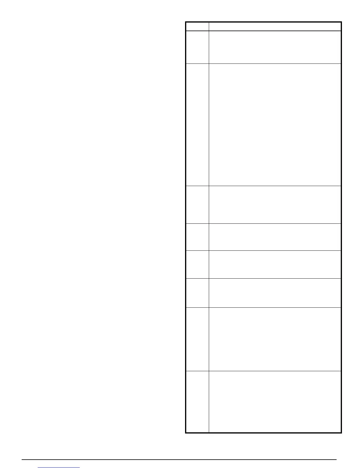
Table 8. Individual Fault Codes
CODES DESCRIPTION
1
9
These codes indicate abnormal high current or high
inverter temperature. If they persist and return as active
fault codes, they may indicate a faulty inverter drive or a
wrong interface board/inverter combination.
Compressor Drive Failure – This generally indicates
a compressor problem which may be temporary or
permanent. If the compressor has just been replaced,
recheck the U, V, and W compressor leads for a
connection mistake.Before the inverter declares this
fault during an attempted startup, it will try to start the
compressor 4 times, with approximately 20 seconds
pause between attempts. During start attempts, listen
for compressor noise; if none, the compressor may need
to be replaced. Check compressor phase-to-phase
resistances; they should all be less than 1.5 ohms
and within 0.2 Ω of each other. If compressor noise is
loud, squealing, or otherwise unusual, the compressor
may need to be replaced. If the compressor restarts
normally, this fault code may be simply an indication that
the compressor speed has been temporarily disrupted
by either starting or shutting down abruptly against a
high pressure ratio. In either case, the system may
be normal but only temporarily affected by abnormal
running conditions.
4
1
11
1
1
These fault codes refer to internal inverter operation and
arelikelytoindicateinverterfailure.Iftheypersistand
return as active fault codes, replace the inverter assembly.
6
– This is an indication that line
voltage exceeded 10% over nominal value. The cause
is likely to be power grid abnormalities or a poorly
controlled generator.
7
– In most cases this is an
indication that 208/230 volt line power was interrupted
or disconnected. It may also indicate low line voltage
or, rarely, an internal inverter failure.
8
– This indicates that line voltage
hasdroppedbelowapproximately170volts.Itmayalso
indicate loss of line power, in which case Code 7 may
appear in addition to or instead of this code.
14
Loss of Communication Between Inverter and
Interface Board – Check the inverter LEDs (as
described in Inverter Circuit Board LEDs section) for
anindicationthattheinverterhaslinepower.Followthe
troubleshooting steps described in that section first. If
theinverterLEDsarelitbutthecodeisactive,verifythat
the 4-pin plug at J5 ) is connected at
the bottom edge center of the interface board. If these
checksdonotresolvethefault and thefaultremains
active, replace the interface board.
1
16
17
These are warning codes that simply indicate that a
high current or temperature condition was reached,
andthattheinverterwasabletokeeptheparameterin
an acceptable range by automatically reducing speed.
These conditions do not result in the unit shutting down
(unless the current or temperature increased further
and reached a shutdown limit, in which case another
code would be displayed). NOTE: If a high current or
temperature shutdown occurs, these warning codes are
not necessarily displayed and stored.