4
ELECTRICAL CONNECTIONS
WARNING:
ELECTRICAL SHOCK HAZARD
Failure to follow safety warnings exactly could
result in serious injury or property damage.
Improper servicing could result in dangerous
operation, serious injury, death or property
damage.
to the unit.
disconnecting. Reconnect wires correctly.
Electrical Power Wiring
Electrical power wiring shall comply with the current
provisionsoftheNationalElectricalCode(ANSI/NFPA70)as
supplemented by applicable local building codes. The installer
shouldbecomefamiliarwiththewiringdiagrambeforemaking
electrical connections to the outdoor unit. An equipment wiring
diagram is included in this instruction (Figure 8 (page 14)
& Figure 9 (page 15) and inside the unit control panel
cover. Refer to the unit rating label located on the exterior of
the control box cover for operating voltage, minimum circuit
ampacity, and maximum fuse size. See Table 1 for wire sizing.
• Electricalconnectionstotheairconditioneraremadeat
the bottom of the control panel compartment. Remove the
control panel cover to gain access to this compartment.
Figure 2 (page 11) shows a typical control panel
compartment.
• Aproperlysizedbranchcircuitanddisconnectswitchmust
be installed where it is easily accessible and within line of
sight of the outdoor unit.
• Remove the control panel cover. Route the power and
ground wires (3 wires, including earth ground) from the
disconnect box to the unit. Use of outdoor shielded conduit
(metal lined Sealtite®) is required. The electrical conduit
opening is located on the right side of the panel forming
the bottom of the control compartment. See Figure2.
• Connect the powerwiresto L1 and L2 box lugs of the
contactor, and the ground wire to the grounding lug located
to the right of the contactor. Refer to Figure2 and Figure
3 (page 12). Only copper wires should be used.
• Replacethecontrolpanelcoverbeforeapplyingpower.
Control Circuit Wiring
The air conditioner is designed to operate with a 24 vac Class
II control circuit. Control circuit wiring must comply with the
latestversionoftheNationalElectricalCode(ANSI/NFPA70)
as supplemented by local building codes.
In general, 24 vac control power wiring must be run to
interconnect the two-stage thermostat, the indoor unit, and
the outdoor unit. The source of the 24 vac is located within the
indoor unit (air handler or furnace). The C side of this power
source may be grounded or ungrounded, typically determined
by the indoor equipment electrical design.
Fourcontrolwiresmustberuntotheairconditioner’scontrol
panel:R and C will originate from the indoor unit (furnace or
air handler). Y1 and Y2 will originate at the thermostat.
Pass each field-run control wire into the hole in the lower left side
ofthebaseoftheairconditioner’scontrolpanelcompartment.
Refer to Figure2 and Figure4(page12). Connect each of
the field-run wires to its corresponding factory wired lead (with
stripped ends) using a wire nut or other solderless connector
within the low voltage compartment. See Table 2 below.
REFRIGERANT LINE CONNECTIONS
Line Design and Routing
Refrigerant lines must be connected by a licensed EPA certified
technician following sound established installation practice.
Once the air conditioner location has been determined and
the unit set in place the refrigerant lines should be routed
and connected.
• Refrigerantlinesshouldfollowadirectpathfromtheindoor
coil to the outdoor unit avoiding sharp bends. When lines
passthroughwalls,makesuretoproperlysealandsupport
them so that vibration is not transmitted to the structure.
• Refrigeranttubingshouldbesupportedinamannerwhich
assures that the tubing will not vibrate or wear as a result
of contact with sharp materials or edges during system
operation.
• Linesmustbecleanrefrigeration-gradecopper.
• Avoidremovingcapsandplugsfromairconditionervalves
or lines until they are ready to be connected.
• Insulatethevaporlinewithrefrigerantlineinsulationwall
thickness¼”orgreater.
Proper system performance and oil management depend
on properly selecting the liquid and vapor line sizes. Refer to
Table 3 below for the proper size of field supplied lines. The
maximum allowable refrigerant line length is 100 ft.
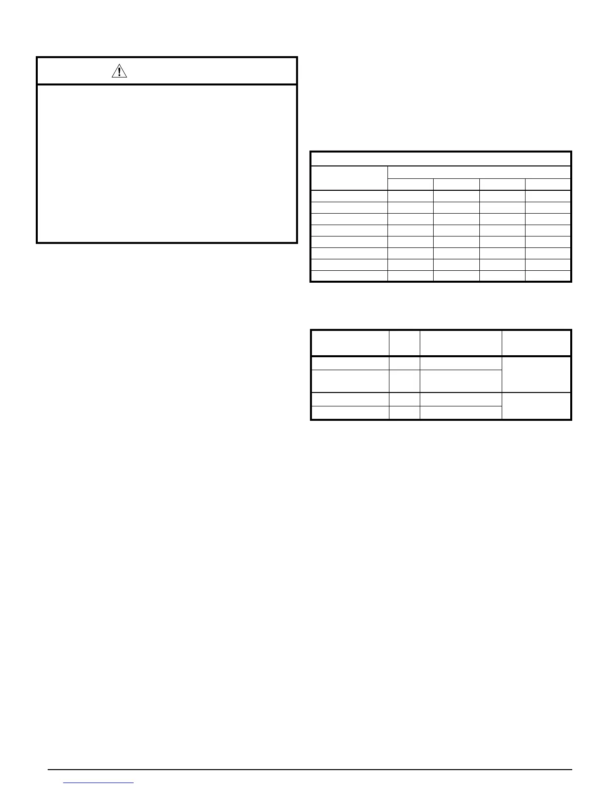
SUPPLY CIRCUIT
AMPACITY
SUPPLY WIRE LENGTH - FT
UP TO 50 51 - 100 101 - 150 151 - 200
15 14 10 8 6
20 12 8 6 4
25 10 8 6 4
30 10 6 4 4
35 8 6 4 3
40 8 6 4 3
45 6 4 3 2
50 6 4 3 2
Wire Sized based on N.E.C. for 60°C type copper conductors
Table 1. Copper Wire Ampacity Tables
WIRE COLOR
ID FUNCTION
INDOOR
CONNECTION
RED
R
24VAC
FurnaceorAir
Handler
BLK
C
24 VAC common
or ground
YEL
Y1
1st Stage call
Thermostat
BLU
Y2
2nd Stage call
Table 2.