7
The actual current operating compressor speed can be
determinedbycheckingthe2-characterdisplayontheinterface
board. Refer to Figure7(page13) and Table5.
Control operation is protected under U.S. patent number
US 8,011,199 B1.
Diagnostic Display
The interface board located inside the control panel has a
two character display which provides information regarding
operational status and fault history. When 24 vac control
power is provided to the board, the display will show some
combination of characters. In order to diagnose a problem
with the unit, or to determine its operational status, remove
the control panel cover, then observe the 2-character lighted
display on the interface board. Refer to Table 5 (page 7)
and Table 6 (page 8).
When control power is first applied to the control board, the
2-character display will show the following three items in
sequence,twice:
• Unitsize(tons):, , 4, or
• Unittype:AC for air conditioner
• Softwareversion,e.g.4.
This power-up display sequence is intended to confirm the
correct programming of the inverter control board.
After power-up, the display will alternate between an operating
code (Table5) and a list of the codes for up to the last 20
different faults or warnings. When this list is being displayed,
eachdiagnosticcodeinmemorywillbedisplayedfor5seconds.
The most recent code will be the first one appearing in the
series of codes displayed.
NOTE: Ifthereisafaultthatis“active”whenthedisplayis
viewed, the decimal point to the right of the right side character
will be lit. The code for the most recent active fault will flash
three times before the remainder of the fault history list is shown.
Faultcodesareretainedthroughlossofpower.Anyfaultwhich
hasbeeninthelistformorethan7days(withcontrolpower
applied) will be removed.
When there are no active faults, the
list of past fault codes can be cleared by shorting the TEST
pins (J4, at the lower right side of the inverter control board)
when the unit is powered up but not running.
NOTE: This action may also have other consequences - See
Short Cycle Timer Override section above.
Short Cycle Timer Override
When performing startup tests or while troubleshooting, the
5minutestartupdelaycanbeskippedbyshortingthetwoJ4
Test pins indicated in Figure7 for about 1 second while the
compressor is off and waiting to start.
NOTE: Use this feature with forethought because it will also
clear the fault codes stored in memory, which can make
troubleshooting more difficult.
Low Temperature Lockouts
The control will not permit the unit to operate at ambient
temperaturesbelow50°F.Ifthereisacallforairconditioning
when the temperature drops below this point, the unit will shut
down (if running), and diagnostic code 9 will be displayed on
the interface board. The status code (forLowTemperature)
willalsoappear.Oncethislockoutisineffect,theunitcan
resume cooling after ambient temperature has risen again
above55°F.
Other Speed Overrides
When ambienttemperature ishigh, exceeding105° F,the
compressor speed may be reduced to limit current draw or
inverter component temperature. Whether or not this occurs
and to what degree the speed is reduced depends upon the
unit model and the specific operating conditions as detected
by the inverter. Speed will return to the normal value when the
high current or temperature condition is relieved. In addition,
anytimeoutdoorambienttemperatureexceeds100°F,the
fan will operate at its maximum speed.
Instrumentation
The 20 SEER iQ Drive split system air conditioner includes
instrumentation as listed in Table 7 (page 8). All items
listed are connected to the interface board except for the high
pressure switch. Refer to Figure2(page11), Figure7(page
13), Figure 8 (page 14), and Figure 9 (page 15). The
two temperature sensors are color coded so that the color of
the wire insulation matches the color of the connector base
on the left side of the circuit board. All temperature sensors
are10kohmthermistors.Theresistancesofthesesensors
(whendisconnectedfromtheinterfaceboard)maybechecked
against Figure 10 (page 16) for troubleshooting purposes.
Figure10 shows the thermistor resistance-temperature curve
brokenintotwopartsforeaseofuse.
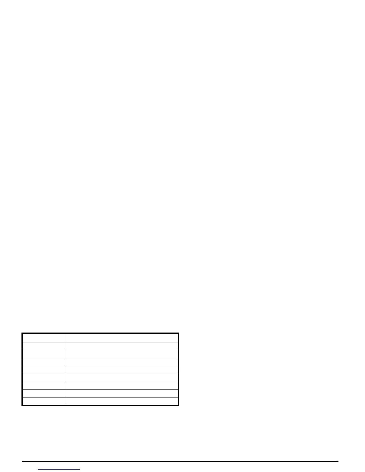
DISPLAY CAPACITY STAGE OR STATUS
C1
Cooling,StageOneCall,Low
C
Cooling, Stage One Call, Intermediate
C
Cooling,StageOneCall,LowHigh
C4
Cooling, Stage Two Call, Nominal High
C
Cooling, Stage Two Call, Boost
C_,d
StartupDelay(5minutes)
_
System Powered but Idle
CoolingLowTemperatureLockout(<50°F)
Table 5. Interface Board Operating Codes