EasyManua.ls Logo

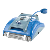
Maytronics Supreme M4 User Manual

Maytronics Supreme M4
28 pages
To Next Page IconTo Next Page
Page #1 background imageLoading...
Page #1 background image
Supreme M4 Assembly Instructions
Page 1 of 18
Table of Contents
1. Assembling the Motor Unit’s Parts ................................................................................................... 2
2. Assembling the Diaphragms ............................................................................................................. 3
3. Assembling the Active Brush ............................................................................................................ 4
4. Assembling the Motor Unit ............................................................................................................... 5
5. Assembling the Driving System and Side Cover ................................................................................ 6
6. Assembling the driving system and Side Cover on the other side of the robot ................................. 9
7. Assembling the Floating Cable ....................................................................................................... 11
8. Positioning the Float ...................................................................................................................... 13
9. Positioning the Brush Covers.......................................................................................................... 14
10. Assembling the Outer Casing........................................................................................................ 15
11. Assembling the Impeller Cover .................................................................................................... 16
12. Assembling the Handle ................................................................................................................. 17
13. Assembling the Brushes ............................................................................................................... 18
Question and Answer IconNeed help?

Do you have a question about the Maytronics Supreme M4 and is the answer not in the manual?

Maytronics Supreme M4 Specifications

General IconGeneral
TypeRobotic Pool Cleaner
Pool TypeIn-ground
Pool SizeUp to 50 feet
Cable Length60 feet
Warranty2 years
FiltrationFine
Power Supply24V

Summary

1. Assembling the Motor Unit's Parts

Step 1.1: Secure the impeller

Secure the impeller using a 4X25 screw for motor unit assembly.

Step 1.2: Secure impeller protector cylinder

Secure the impeller protector cylinder with four KA50X12 screws.

2. Assembling the Diaphragms

Step 2.1: Insert diaphragms

Insert two diaphragms into the designated positions on the robot.

3. Assembling the Active Brush

Step 3.1: Place active brush

Place the active brush into its correct position on the robot frame.

Step 3.2: Secure active brush

Secure the active brush using four KA50X20 screws.

4. Assembling the Motor Unit

Step 4.1: Position motor unit

Position the motor unit into the frame, ensuring correct orientation.

Step 4.2: Secure motor unit

Secure the motor unit to the frame using four KA50X20 screws.

5. Assembling the Driving System and Side Cover

Step 5.1: Place guide wheels

Place the guide wheels onto the side of the motor shaft.

Step 5.2: Insert hexagon adaptor

Insert the hexagon adaptor into the pulley component.

Step 5.3: Position pulley and gear

Position the pulley and the Active Brush gear into their respective places.

Step 5.4: Place track

Place the track onto both sides of the robot as indicated.

Step 5.5: Assemble track safety cover

Assemble the track safety cover onto the side panel.

Step 5.6: Insert side panel

Insert the side panel into its correct position.

Step 5.8: Secure side panel

Secure the side panel in place using four KA50X20 screws.

Step 5.9: Check side panel clips

Ensure the side panel clips are properly seated in place.

6. Assembling the Driving System and Side Cover on the Other Side

Step 6.1: Place guide wheels and pulley

Place the guide wheels and pulley on the other side of the robot frame.

Step 6.2: Position track

Position the track into place as shown in the diagram.

Step 6.3: Assemble side panel with fins facing out

Assemble the side panel ensuring the fins are facing outwards.

Step 6.4: Check side panel clips

Verify that the side panel clips are in their correct positions.

Step 6.5: Secure side panel

Secure the side panel in place using four KA50X20 screws.

7. Assembling the Floating Cable

Step 7.1: Insert floating cable

Insert the floating cable into the motor unit terminal.

Step 7.2: Connect cable retrofit

Connect the cable's retrofit to the motor unit, matching the slot shape.

Step 7.3: Press seal firmly

Press the seal firmly against the terminal for a secure connection.

Step 7.4: Tighten nut by hand

Tighten the nut securely by hand to fasten the cable.

Step 7.5: Position floating cable

Position the floating cable correctly on the motor unit.

Step 7.6: Cable position on motor unit

Ensure the cable is in the correct position on the motor unit.

Step 7.7: Secure cable holders

Secure the cable holders using four KA50X12 screws.

8. Positioning the Float

Step 8.1: Place float on motor unit

Place the float onto the motor unit, specifically on the drive motor side.

9. Positioning the Brush Covers

Step 9.1: Position brush safety covers

Position the two brush safety covers onto the robot.

10. Assembling the Outer Casing

Step 10.1: Place outer casing

Place the outer casing onto the robot frame.

Step 10.2: Secure outer casing

Secure the outer casing to the frame with four KA50X20 screws.

11. Assembling the Impeller Cover

Step 11.1: Place cable support

Place the cable support on the outer casing before closing the impeller cover.

Step 11.2: Position impeller cover diagonally

Position the impeller cover diagonally onto the outer casing.

Step 11.3: Secure impeller cover

Secure the impeller cover with a KA50X12 screw.

12. Assembling the Handle

Step 12.1: Position the handle

Position the handle correctly onto the robot assembly.

Step 12.2: Secure the handle

Secure the handle in place using two KA50X20 screws.

13. Assembling the Brushes

Step 13.1: Place one brush

Place one brush into its designated position on the robot.

Step 13.2: Place second brush

Place the second brush by pulling it towards you into its position.

1. Dismantling the Handle

Step 1.1: Unscrew handle screws

Unscrew the two screws holding the handle in place.

Step 1.2: Remove the handle

Take the handle off the robot assembly.

2. Dismantling the Impeller Cover

Step 2.1: Unscrew impeller cover screw

Unscrew the single screw holding the impeller cover in place.

Step 2.2: Remove impeller cover

Lift the impeller cover from one side and then remove it.

3. Dismantling the Outer Casing

Step 3.1: Unscrew outer casing screws

Unscrew the four screws securing the outer casing.

Step 3.2: Remove black grommet

Remove the black grommet before detaching the outer casing.

Step 3.3: Pull outer casing up

Hold the outer casing on both sides and pull it upwards.

4. Dismantling the Cable

Step 4.1: Remove float from motor unit

Remove the float component from the motor unit.

Step 4.2: Unscrew cable holder screws

Unscrew the four screws securing the cable holder.

Step 4.3: Unscrew cable from motor unit

Unscrew the cable connection from the motor unit.

Step 4.4: Unplug the cable

Unplug the floating cable from its terminal.

5. Disassembling the Motor Unit

Step 5.1: Unscrew motor unit screws

Unscrew the four screws that secure the motor unit to the frame.

Step 5.2: Remove the motor unit

Carefully remove the motor unit from the robot's chassis.

Step 5.3: Remove hexagon adapter

Remove the hexagon adapter from its seated position.

6. Dismantling the Side Panels

Step 6.1: Unscrew side panel screws

Unscrew the four screws holding each side panel in place.

Step 6.2: Pull side panels off

Gently pull the side panels away from the robot body.

7. Dismantling the Driving System

Step 7.1: Remove pulley and track from one side

Remove the pulley and track assembly from one side of the robot.

Step 7.2: Remove guide wheels

Remove the guide wheels from their mounting points.

Step 7.3: Remove pulley, track, and drive wheel from other side

Remove the pulley, track, and drive wheel from the opposite side.

8. Dismantling the Brushes

Step 8.1: Remove brushes

Remove both the standard and active brushes from the robot.

Step 8.2: Unscrew active brush screws

Unscrew the four screws that hold the active brush in place.

Step 8.3: Remove the Active Brush

Remove the active brush after its screws are undone.

9. Dismantling the Diaphragms

Step 9.1: Remove diaphragms

Remove the two diaphragms from the robot's internal structure.

Related product manuals