EasyManua.ls Logo

Maytronics Supreme M3 User Manual

Maytronics Supreme M3
23 pages
To Next Page IconTo Next Page
Page #1 background imageLoading...
Page #1 background image
Supreme M3 Assembly
Table of Contents
1. Assembling the Motor Unit ............................................................................................................... 5
2. Assembling the Driving System and Side Cover ................................................................................ 6
3. Assembling the Driving System and Side Cover on the other side of the robot ................................. 9
4. Assembling the floating cable ........................................................................................................ 10
5. Positioning the Float ...................................................................................................................... 12
6. Assembling the Outer Casing ......................................................................................................... 13
7. Assembling the Impeller Cover ...................................................................................................... 14
8. Assembling the Brushes ................................................................................................................. 15
Question and Answer IconNeed help?

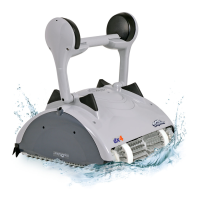
Do you have a question about the Maytronics Supreme M3 and is the answer not in the manual?

Maytronics Supreme M3 Specifications

General IconGeneral
TypeRobotic
Pool TypeIn-ground
Voltage24V
Warranty2 years
Pool SizeUp to 50 ft
Cleaning CoverageFloor, Walls
Filter TypeFine filter
Cable Length60 feet
Power Supply110-240V

Summary

1. Assembling the Motor Unit

Step 1.1 Assemble the cover cork into the Pulley's place

Assemble the cover cork into the pulley's designated position.

Step 1.2 Place the motor unit in its place

Position the motor unit correctly within the assembly frame.

Step 1.3 Secure the motor unit to the frame with 4X KA50X30

Fasten the motor unit to the frame using four KA50X30 screws.

2. Assembling the Driving System and Side Cover

Step 2.1 Place the guide wheels on the side of the motor shaft

Install the guide wheels onto the motor shaft.

Step 2.2 Insert the hexagon adaptor into the Pulley

Insert the hexagon adaptor into the pulley component.

Step 2.3 Place the track on the Pulley

Position the track correctly onto the pulley.

Step 2.4 Put the Pulley And the track in their places

Install the pulley and track assembly into their final positions.

Step 2.5 Put the side panel with the wheel on the drive motor side

Attach the side panel with the wheel to the drive motor side.

Step 2.6 Press on the bottom of the side panel to fit the clips into their places

Secure the side panel by pressing its bottom clips into place.

Step 2.7 Secure the side panel in place with 4 KA40X20 screws

Fasten the side panel using four KA40X20 screws.

3. Assembling the Driving System and Side Cover on the other side of the robot

Step 3.1 Put the shorter track on the other side of the robot as shown

Install the shorter track on the opposite side of the robot.

Step 3.2 Put the side panel with the fins into its place

Place the side panel, ensuring the fins are correctly positioned.

Step 3.3 Secure the side panel in place with 4 KA40X20 screws

Fasten the side panel using four KA40X20 screws.

4. Assembling the floating cable

Step 4.1 Pass the cable through the outer casing as shown

Route the cable through the outer casing as illustrated.

Step 4.2 Insert the floating cable to the motor unit

Connect the floating cable to the motor unit.

Step 4.3 Press the seal firmly to the terminal

Ensure the seal is pressed firmly onto the terminal.

Step 4.4 Tighten the plastic screw properly with the special torque key

Tighten the plastic screw using the provided torque key.

Step 4.5 Position the cable on the motor unit and secure the cable holder with 4Χ ΚΑ50Χ12

Mount the cable on the motor unit and secure the holder with 4 KA50X12 screws.

5. Positioning the Float

Step 5.1 Place the float on the motor unit, on the drive motor side as shown

Position the float on the motor unit's drive motor side.

6. Assembling the Outer Casing

Step 6.1 Place the outer casing on the frame

Mount the outer casing onto the robot's frame.

Step 6.2 Make sure the casing seats well on the side panel slots

Ensure the outer casing correctly engages with the side panel slots.

Step 6.3 Secure the outer casing to the frame with 4X KA 50x25

Fasten the outer casing to the frame using four KA 50x25 screws.

7. Assembling the Impeller Cover

Step 7.1 Place the cable spring in its place on the outer casing before closing the impeller cover

Position the cable spring on the outer casing before attaching the impeller cover.

Step 7.2 Position the impeller cover diagonally on the outer casing as shown

Orient the impeller cover diagonally onto the outer casing.

Step 7.3 Secure the impeller cover with a KA50X12 screw

Fasten the impeller cover with one KA50X12 screw.

8. Assembling the Brushes

Step 8.1 Place one brush in place

Install the first brush into its designated position.

Step 8.3 Place the second brush in its place by pushing it strongly away from you

Install the second brush by pushing it firmly away from the user.

1. Dismantling the Impeller Cover

Step 1.1 Unscrew the 3 screws holding the cover in place

Remove the three screws securing the impeller cover.

Step 1.2 Lift the cover off

Gently lift and remove the impeller cover.

2. Dismantling the Outer Casing

Step 2.1 Unscrew the 4 screws holding the cover in place

Remove the four screws securing the outer casing.

Step 2.2 Hold the outer casing on both sides. Pull it up to remove it

Grasp the outer casing on both sides and lift it upwards.

3. Dismantling the Cable

Step 3.1 Dismantle the 2 screws on the cable holder

Remove the two screws from the cable holder.

Step 3.2 Remove the float from the motor unit

Detach the float from the motor unit.

Step 3.3 Release the cable from the motor unit, using the Terminal Key

Use the Terminal Key to disconnect the cable from the motor unit.

Step 3.4 Unplug the cable

Disconnect the floating cable.

4. Dismantling the Motor Unit

Step 4.1 Unscrew the 4 screws holding the motor unit in place

Remove the four screws securing the motor unit.

Step 4.2 Remove the motor unit

Lift and remove the motor unit from the frame.

Step 4.3 Remove the hexagon adaptor

Detach the hexagon adaptor from its mount.

5. Dismantling the Side Panels

Step 5.2 Pull the side panels off

Remove the side panels by pulling them away from the robot.

6. Dismantling the Drive System

Step 6.1 Remove the pulley together with the track

Detach the pulley and its associated track.

Step 6.2 Remove the guide wheels

Remove the guide wheels from the drive system.

Step 6.3 Remove the tracks

Detach the tracks from the robot's drive mechanism.

Step 6.4 Remove the brushes

Detach the brushes from the robot.

Related product manuals