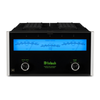
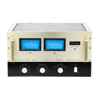
Ordinary meters lack the capability of indicating
the short interval power in a sound wave. The
mass of the meter movement is too great to re-
spond to instantaneous changes in music pro-
gram material. Mclntosh superior engineering
has developed new circuitry that permits the
meters on the MC2505 to respond to the short
interval power in a sound wave to an accuracy of
98% of the true value. This is another Mclntosh
development that represents a major step for-
ward in the use of power level meters.
There are two circuits that give these meters
the indicating capability of the short interval
power in a sound wave. The first circuit is an
accelerating circuit that compensates for the
inertia characteristics of the meter movement.
Because the short interval power fluctuation is
so rapid, the eye might not perceive the instan-
taneous power reading. This caused the devel-
opment of the second circuit, which is a "time
stretching" circuit. The time stretching circuit
delays the movement of the meter needle at
peak reading for a few milliseconds.
With the aid of the CBS test record STR100, the
frequency response of your phono cartridge can
be measured. The graph on page 5 shows the
ideal RIAA curve using the CBS record STR100.
Follow these steps to plot the performance of
your phonograph cartridge.
1. Set the "METER RANGE SWITCH" to the
—20
position.
2. Play the 1000 Hz test tone recorded on
the CBS Test Record STR100 on your
phonograph.
3. Turn the "LEFT GAIN" control until the
left meter indicates "0."
4. Turn the "RIGHT GAIN" control until the
right meter indicates "O."
5. Write down the meter indication at each
frequency as the record plays.
6. Transfer the readings by frequency to
the graph.
7. The graph shows the ideal RIAA re-
sponse curve using the CBS #STR100 test
record. Compare your curve with the curve
on the graph. A deviation of 3 dB from the
ideal is acceptable. By making this check
at regular intervals, (for instance, every 6
months) any deterioration in the cartridge
or system will be quickly detected.
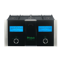
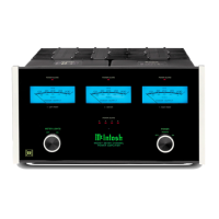
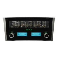
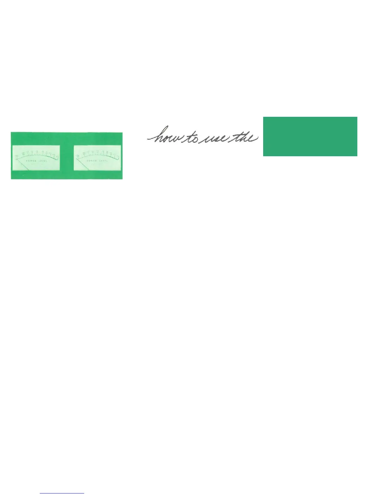
DYNAMIC PEAK
LOCKING METERS
A tape recorder can be checked in the same
fashion.
1. Use a standard frequency response tape
as the signal source.
2. Complete all steps outlined for phono
cartridges.
3. You now have a graph of the playback
characteristics of your tape recorder.
To find the record characteristics of the tape
recorder follow this procedure:
1. Record the CBS Test Record #STR100
on your tape recorder. Adjust the record
volume only on the 1000 Hz signal for
proper recording level. DO NOT ADJUST
THE RECORD VOLUME CONTROL DUR-
ING THE RECORDING.
2. Play back the tape just recorded. Com-
plete all steps outlined for tape playback
characteristics.
3. A comparison of the two curves will give
the recording characteristics of your tape
recorder. A deviation of 3 dB is acceptable.
Similar checks can be made on all program
sources in your stereo system. Follow the same
general procedure for any program source for
which a standard reference is available.
•1
 Loading...