INSTALLATION
Adequate ventilation extends the trouble-free life of
electronic instruments. It is generally found that each
10° centigrade (18° F) rise in temperature reduces
the life of electrical insulation by one half. Adequate
ventilation is an inexpensive and effective means of pre-
venting insulation breakdown that results from unnec-
essarliy high operating temperatures. The direct benefit
of adequate ventilation is longer, trouble-free life.
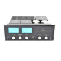
The suggested minimum space for mounting the
MC 2505 is 14 inches long x 16½ inches wide x 6 inches
high. Always allow for air flow by either ventilation
holes or space next to the bottom of the amplifier and
a means for the warm air escape at the top.
It is recommended that the MC2505 be mounted in a
normal or horizontal position. However, with adequate
ventilation the amplifier can be mounted in any position.
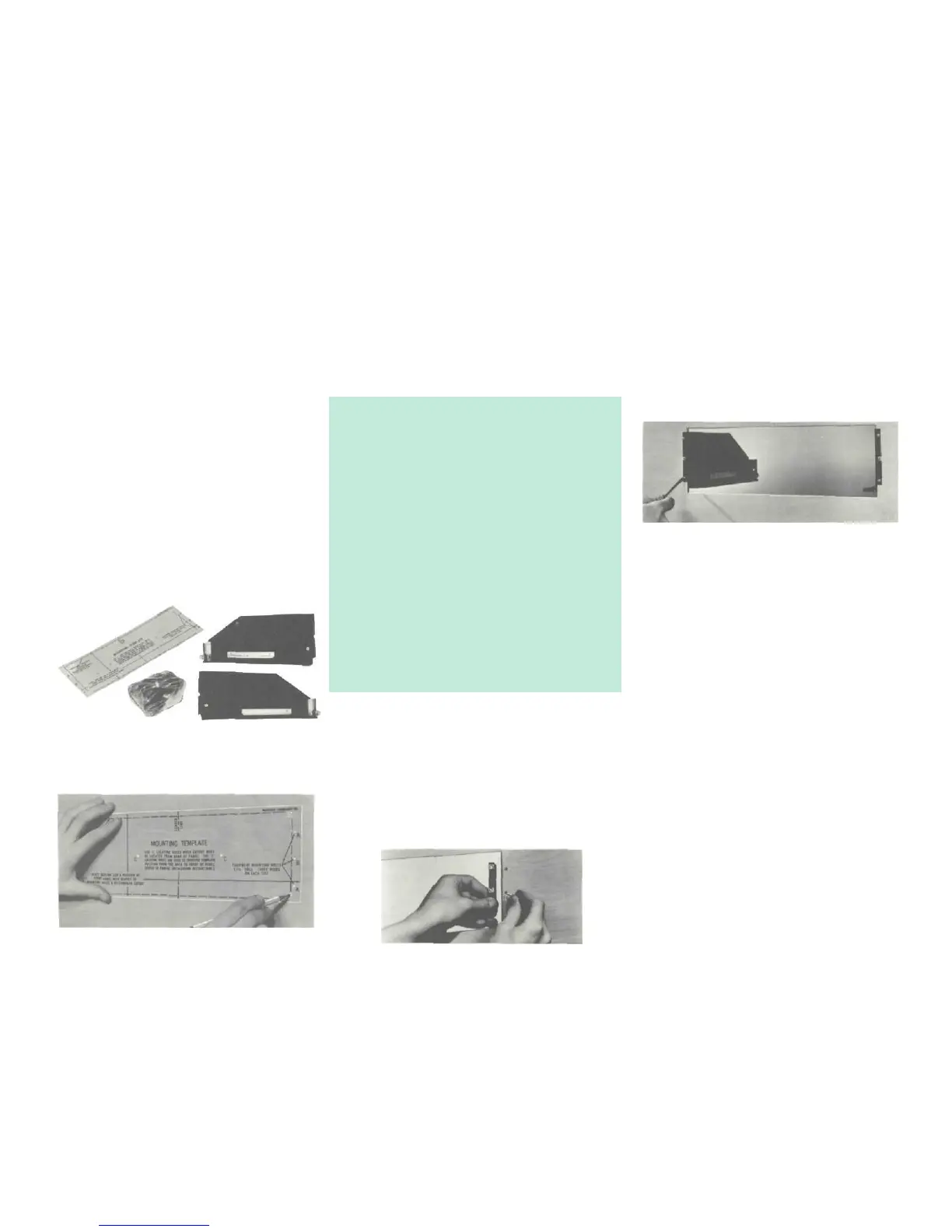
To prepare the MC2505 for installation remove the
plastic protective covering. Turn the MC 2505 upside
down so that it rests on its top on the shipping pallet.
Remove the four plastic feet fastened to the bottom
of the chassis.
Next place the mounting brackets, the parts bag and
the mounting template for easy accessibility.
The professional mounting design eliminates the need
for any shelf or bracket to support the MC2505. It is
completely supported by its own mounting brackets.
If the cutout is to be located from the rear of the panel,
the following steps will help you.
On the back of the cabinet panel, scribe a vertical
centerline through the exact center of the area in which
the cutout is to be made.
Place the template against the back of the panel and
match the template centerline with the centerline on the
cabinet panel.
Make sure that there is at least ¼ inch clearance be-
tween the bottom of the dashed line of the cutout area
on the template and any shelf or brace below the pro-
posed cutout.
Mark the two locating holes ("C" holes on the mount-
ing template).
Drill the two locating holes. Be certain the drill is per-
pendicular to the panel.
Now position the template on the front of the panel by
aligning the "C" locating holes on the template with
the drill holes.
With the saw on the INSIDE OF THE PENCIL LINES
carefully cut out the rectangular opening.
Position the plastic mounting template over the area
Secure the mounting strips to the rear of the cabinet
panel using two screws from the hardware package.
Insert the screws in the center holes of the cabinet
panel ("B" holes on the template) and tighten. The
screw head should pull into the wood slightly. (Use two
¾ inch long screws for panels under ½ inch, or two 1¼
inch long screws for panels ½ inch thick and larger.)
Attach the mounting brackets to the cabinet panel us-
ing four screws.
Place the template over the mounting screws. The
mounting screws should be centered in the "A" and
'B" holes on the template. The sides of the mounting
brackets should match the vertical dash lines on the
template. If necessary, loosen the screws and push the
brackets into alignment and retighten.
Insert the power cord through the opening. Carefully
slide the MC 2505 into the opening so the rails on
the bottom of the equipment slide in the track of the
mounting brackets. Continue to slide the instrument in
until the front panel is against the cabinet panel.
At the bottom front corners of the PANLOC instruments
are the PANLOC buttons.
Depressing the PANLOC buttons will lock the instru-
ment firmly in the installation.
Depressing the PANLOC buttons a second time (as
with a ball-point pen) will release the instrument. You
can then slide the instrument forward to the inspection-
adjustment position.
Depressing the inspection-adjustment position latches
will allow the instrument to be slid completely out of
the installation.
VERTICAL INSTALLATION
In the hardware packet are two helical springs. Fasten
the springs to the small flanges at the rear of the
PANLOC brackets. The flange has a notch and a hole
to mount the spring. The springs assist in the removal
of vertically mounted PANLOC equipment.
DO NOT USE THE SPRINGS ON HORIZONTALLY MOUNTED EQUIPMENT.
11
of the cabinet panel to be cut out for installation.
The design of the mounting template allows you to
position or locate the cutout from the front or rear of
the panel to which the instrument is to be mounted.
With the template in place against the cabinet panel,
mark the "A" and "B" drill holes and the four small
holes that identify corners of the cutout. Join the corner
marks with a pencil. The edge of the template can be
used as a straight edge.
IMPORTANT: DRILL THE 6 HOLES BEFORE MAKING
THE CUTOUT
Accurately drill the three holes on each side of the cut-
out area with a
3
/
16
inch drill.
 Loading...