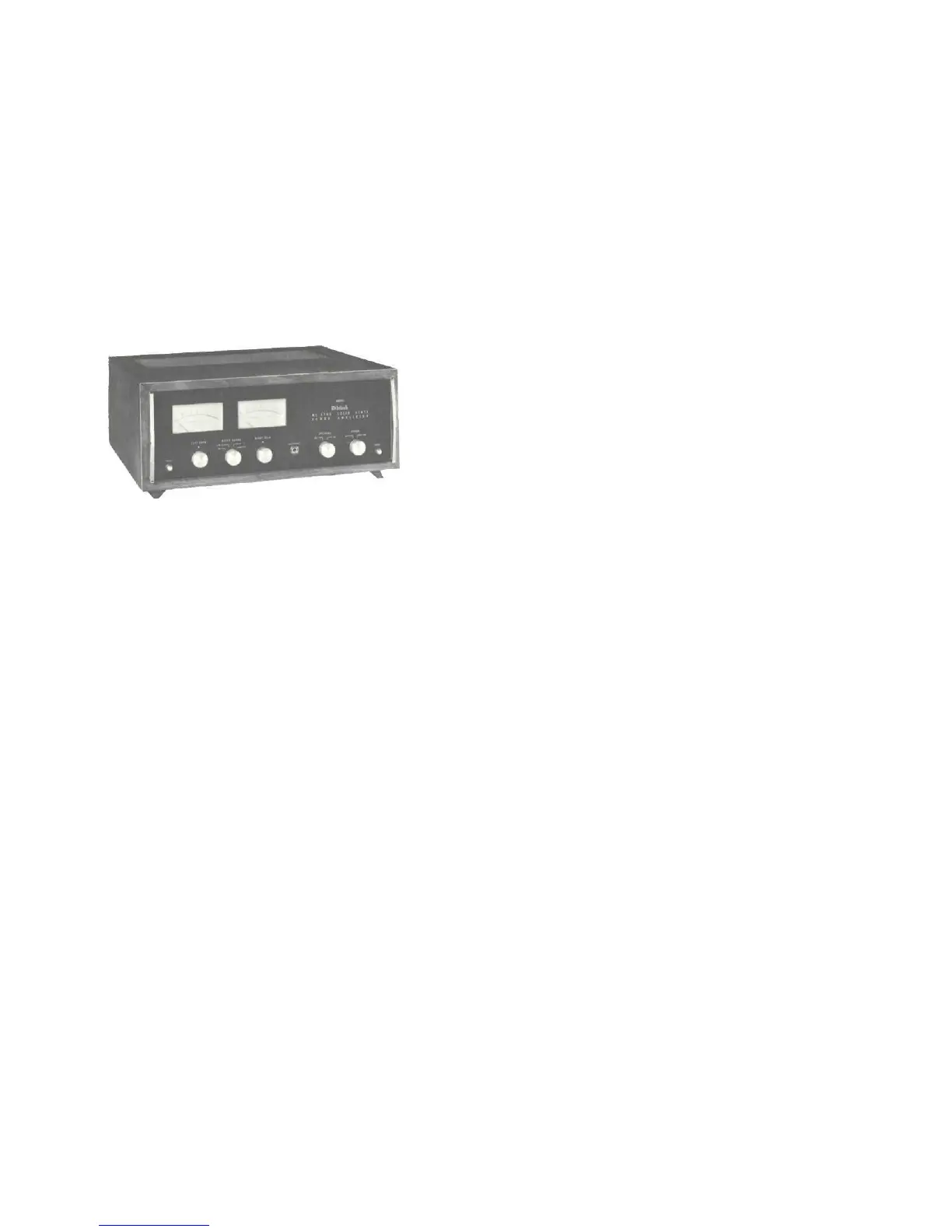
CONNECTING THE MC2505
INPUT-STEREO
The shielded cable from the left output of the Mclntosh
preamplifier is plugged into the left jack. The shielded
cable from the right output of the Mclntosh preamplifier
is plugged into the right jack.
SPEAKERS
Speakers are connected at the barrier strips marked OUT-
PUT on the back panel of the amplifier. Use lamp cord,
bell wire, or wire with similar type of insulation to connect
the speakers to the amplifier. For the normally short dis-
tances of under 50 feet between the amplifier and speaker,
#18 wire or larger can be used. For distances over 50 feet
between the amplifier and speaker use larger wire.
The loudspeaker impedance is usually identified on the
loudspeaker itself. Connect one of the leads from the left
loudspeaker to the screw marked COM on the LEFT OUT-
PUT barrier strip. Connect the other lead from the left
loudspeaker to the screw marked with the number cor-
responding to the speaker impedance on the LEFT OUT-
PUT barrier strip. Connect one of the leads from the right
loudspeaker to the screw marked COM on the RIGHT
OUTPUT barrier strip. Connect the other lead from the
right loudspeaker to the screw marked with the number
corresponding to the speaker impedance on the RIGHT
OUTPUT barrier strip.
The only adverse effect on the operation of a Mclntosh
amplifier when it is improperly matched is a reduction in
the amount of distortion-free power available to the loud-
speaker. Close impedance matching is desirable for maxi-
mum distortion-free power.
SPEAKER CONNECTIONS
Use this table to determine proper speaker connection:
Connect the
If the speaker impedance speaker leads
is between: between COM and:
3.2 to 6.5 ohms 4 ohms
6.5 to 13 ohms 8 ohms
13 to 26 ohms 16 ohms
Connect as follows:
If the speaker
impedance is:
4 ohms
8 ohms
16 ohms
Connect one left
speaker to screw
LEFT-COM and
other to:
LEFT-4
LEFT-8
LEFT-16
Connect one right
speaker lead to
the screw marked
RIGHT-COM and
the other to:
RlGHT-4
RIGHT-8
RlGHT-16
A MONOPHONIC LOUDSPEAKER
TO BOTH TERMINALS.
THE LOUDSPEAKER CAN BE DAMAGED.
For 25 volt line operation connect one of the left leads to the
screw marked COM on the LEFT OUTPUT barrier strip. The
other left lead is connected to the screw marked 16 on the
LEFT OUTPUT barrier strip. Connect the right leads in the
same manner on the RIGHT OUTPUT barrier strip.
AC POWER:
The MC2505 operates on 117 to 130 volt, 50/60 Hz. The
amplifier will be turned on and off if its power cord is plug-
ged in one of the auxiliary AC outlets on the program source.
13
DO NOT CONNECT
 Loading...