8
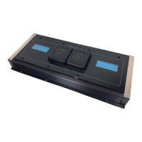
How to Connect for Two Channels
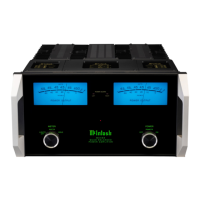
Left Tweeter Left Woofer/Midrange
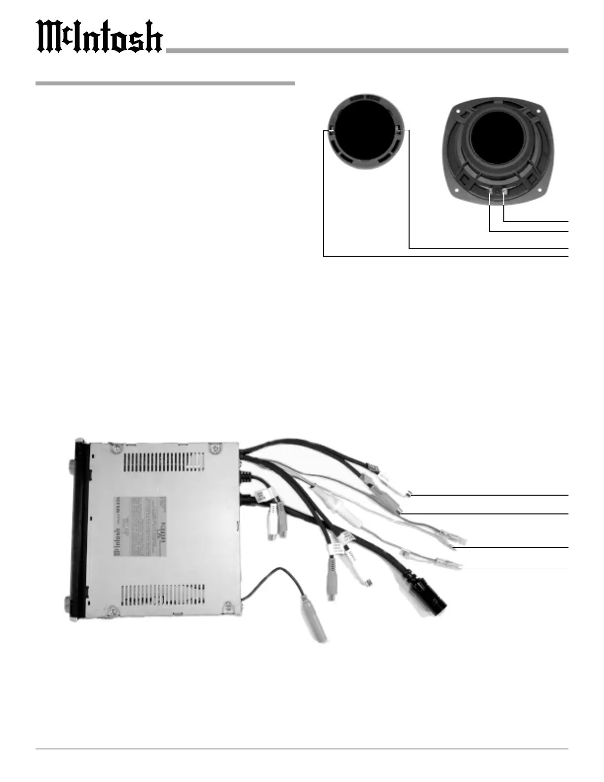
1. Connect the power control cable from the Control Cen-
ter Amp ON to the MCC602TM ON Connector on the
right side of the Amplifier.
Note: All cables should be connected to the amplifier before
connecting the DC power cables to the battery.
2. Connect a cable from a McIntosh Control Center with
Power Guard to the MCC602TM PG Connector on the
right side of the amplifier.
3. Connect the CHANNEL 1 4(-) Ohm OUTPUT of the
Power Amplifier to the Crossover Network Negative
(-) Input Terminal and the CHANNEL 1 4(+) Ohm
OUTPUT to the Crossover Network (+) Input Termi-
nal. Connect the CHANNEL 2 OUTPUTs to the sec-
ond Crossover Network in a similar manor.
4. Connect the cables from the Crossover Network to the
respective Woofer/Midrange Terminals, for both chan-
nels.
5. Connect the cables from the Crossover Network to the
Tweeter Terminals, for both channels.
6. Connect audio cables from the Control Center Front
Outputs to the appropriate MCC602TM Inputs.
7. Connect the MCC602TM DC input terminals on the
left side of the amplifier to the vehicle battery termi-
nals using a minimum size of 4 AWG cables.
Note: It is advisable to place an in-line fuse as close as
possible to the battery.
McIntosh Control Center
Left Front Output
Right Front Output
Amp ON
(blue/white)
Power Guard
(orange)
www.freeservicemanuals.info
Digitized in Heiloo Netherland
 Loading...