IOM 686 AGZ 030A through 065A 77
Trouble Analysis for the AGZ MicroTech Controller
Microprocessor Control Board
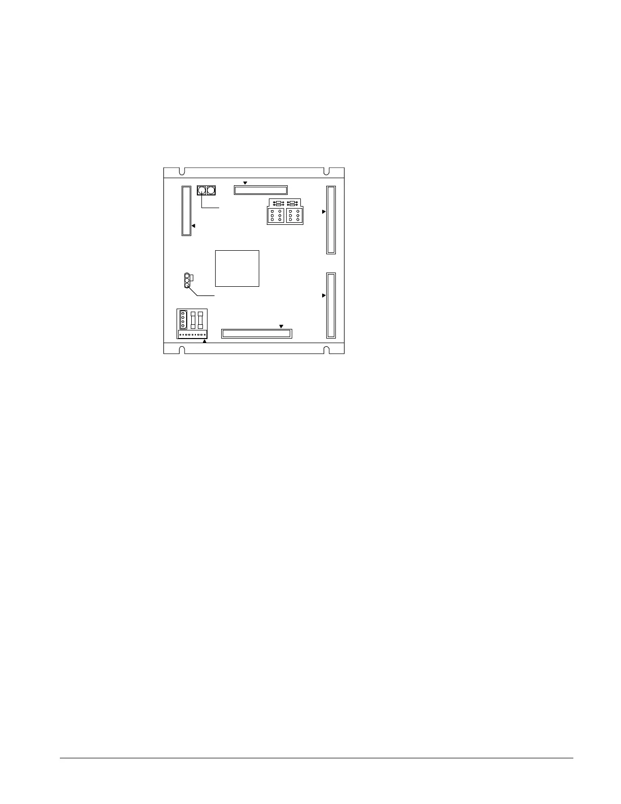
The Microprocessor Control Board (MCB) is shown in Figure 26. It contains a microprocessor that is
preprogrammed with the software required to monitor and control the chiller. The various MCB
connections and components are described below.
Figure 26, Microprocessor Control Board (MCB)
RUNNING
RESET
ACTIVE OUTPUT 0
CPU
STATUS
POWER FUSES
[BUSSMAN GDC-T2A]
POWER IN
[18-24 VCT]
AC AC GND GND
AUX/OUT
DIGITAL OUTPUTS
ANALOG INPUTS DIGITAL INPUTS
HI
ADDRESS
LO
KEYPAD/LCD DISPLAY
COMMUNICATIONS
PORT A PORT B
[FUSE: BUSSMAN MCR-1/4]
FUSE 1
2
3
4
Hex switches
Microprocessor status LED's
EXPANSION BUS
Digital Inputs Connection
The MCB receives digital inputs from the Analog Digital Input (ADI) board through the Digital Inputs
connector via a plug-in ribbon cable. These inputs are conditioned by the ADI board.
Analog Inputs Connection
The MCB receives conditioned analog inputs from the ADI board through the Analog Inputs connector
via a plug-in ribbon cable. These inputs are conditioned by the ADI board. After having been
conditioned, all analog inputs enter the MCB through the Analog Inputs port as 0–5 Vdc signals.
Digital Outputs Connection
After processing all input conditions, the MCB sends the appropriate output signals to output devices
through the Digital Outputs port via a plug-in ribbon cable.
Power In Connector
The MCB receives 18 Vac, center-tapped power from transformer T4 through the Power In connector.
This power drives all logic and communications circuitry
Power Fuses
Two identical 2-amp fuses are located to the right of the Power In connector. These fuses are in the
MCB power supply circuit.
Microprocessor Status LEDs
The green, red, and amber LEDs on the MCB provide information about the operating status of the
microprocessor. The amber LED also indicates the existence of alarm conditions.
 Loading...


