12 IM 676
Physical Data
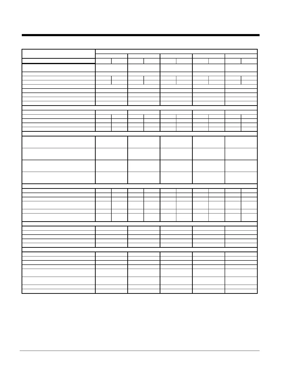
Table 7 , Physical data ALR032E Through 050E
PHYSICAL DATA ALR MODEL NUMBER
032E 035E 040E 045E 050E
BASIC DATA Ckt.1 Ckt.2 Ckt.1 Ckt.2 Ckt.1 Ckt.2 Ckt.1 Ckt.2 Ckt.1 Ckt.2
Unit Capacity @ ARI Conditions (1),
Tons (kW)
32.5 (114.3) 34.6 (121.7) 40.4 (142.0) 45.9 (161.4) 50.8 (178.6)
Number Of Refrigerant Circuits 2 2 2 2 2
Unit Operating Charge, R-22, lb. 20 20 23 23 30 30 32 32 32 32
Unit Operating Charge, R-22, (kg) (9.1) (9.1) (11.3) (11.3) (13.6) (13.6) (13.6) (13.6) (13.6) (13.6)
Cabinet Dimensions, LxWxH, In. 123 x 83 x 59 123 x 83 x 59 123 x 83 x 59 176 x 83 x 59 176 x 83 x 59
Cabinet Dimensions, LxWxH, (mm) (3124 x 2108 x 1499) (3124 x 2108 x 1499) (3124 x 2108 x 1499) (4470 x 2108 x 1499) (4470 x 2108 x 1499)
Unit Operating Weight, Lb. (kg) 4045 (1835) 4065(1853) 4180 (1896) 4765 (2162) 4840 (2196)
Unit Shipping Weight, Lb. (kg) 3895 (1767) 3915 (1785) 4030 (1828) 4615 (2094) 4690 (2127)
Add'l Weight If Copper Finned Coils, Lb. (kg) 270 (122) 270 (122) 370 (168) 410 (186) 410 (186)
COMPRESSORS
Type Semi-Hermetic Semi-Hermetic Semi-Hermetic Semi-Hermetic Semi-Hermetic
Nominal Horsepower 20 20 20 22 25 25 25 30 30 30
Number Of Cylinders Per Compressor 4 4 4 4 4 4 4 6 4 6
Oil Charge Per Compressor, Oz. 130 130 130 130 130 130 130 140 140 140
Oil Charge Per Compressor, (g) (3686) (3686) (3686) (3686) (3686) (3686) (3686) (3969) (3969) (3969)
CAPACITY REDUCTION STEPS - PERCENT OF COMPRESSOR DISPLACEMENT
Standard Staging - Circuit #1 in Lead
Standard 4 Stages 0-25-50-75-100 0-22-50-72-100 0-25-50-75-100 0-21-60-81-100 0-23-59-82-100
Standard Staging - Circuit #2 in Lead
Standard 4 Stages 0-25-50-75-100 0-28-50-78-100 0-25-50-75-100 0-39-60-79-100 0-36-59-77-100
Optional Staging - Circuit #1 in Lead
Optional 6 Stages N/A N/A N/A N/A N/A
Optional Staging - Circuit #2 in Lead
Optional 6 Stages N/A N/A N/A N/A N/A
CONDENSERS - HIGH EFFICIENCY FIN AND TUBE TYPE WITH INTEGRAL SUBCOOLING
Coil Face Area,Sq. Ft. 28.3 28.3 28.3 28.3 28.3 28.3 43.1 43.1 43.1 43.1
Coil Face Area, (M
) (2.6) (2.6) (2.6) (2.6) (2.6) (2.6) (4) (4) (4) (4)
Finned Height x Finned Length, In. 40 x 102 40 x 102 40 x 102 40 x 102 40 x 102 40 x 102 40 x 155 40 x 155 40 x 155 40 x 155
Finned Height x Finned Length, (mm) (1016 x
2591)
(1016 x
2591)
(1016 x
2591)
(1016 x
2591)
(1016 x
2591)
(1016 x
2591)
(1016 x
3937)
(1016 x
3937)
(1016 x
3937)
(1016 x
3937)
Fins Per Inch x Rows Deep 16 x 2 16 x 2 16 x 2 16 x 2 16 x 3 16 x 3 16 x 2 16 x 2 16 x 2 16 x 2
Maximum Relief Valve Pressure Setting, psig
(kPa)
450
(3103)
450
(3103)
450
(3103)
450
(3103)
450
(3103)
450
(3103)
450
(3103)
450
(3103)
450
(3103)
450
(3103)
CONDENSER FANS - DIRECT DRIVE PROPELLER TYPE
Number Of Fans - Fan Diameter, In. (mm) 4 - 26 (660) 4 - 26 (660) 4 - 26 (660) 6 - 26 (660) 6 - 26 (660)
Number Of Motors - HP (kW) 4 - 1.0 (.7) 4 - 1.0 (.7) 4 - 1.0 (.7) 6 - 1.0 (.7) 6 - 1.0 (.7)
Fan And Motor RPM, 60/50Hz 1100/915 1100/915 1100/915 1100/915 1100/915
60 Hz Fan Tip Speed, FPM 7760 7760 7760 7760 7760
60 Hz Total Unit Airflow, CFM 28400 29840 26980 42000 42000
DIRECT EXPANSION EVAPORATOR - BAFFLED SHELL AND THRU-TUBE
Diameter, in. - Length, Ft. 10 - 08 10 - 08 10 - 08 10 - 08 12 - 08
Diameter, (mm) - Length, (mm) (254 - 2439) (254 - 2439) (254 - 2439) (254 - 2439) (305 - 2439)
Water Volume, Gallons, (L) 17.90 (67.8) 17.90 (67.8) 17.90 (67.8) 17.90 (67.8) 24.30 (92)
Maximum Water Pressure, psig (kPa) 175 (1207) 175 (1207) 175 (1207) 175 (1207) 175 (1207)
Maximum Refrigerant Working Pressure, psig
(kPa)
225 (1552) 225 (1552) 225 (1552) 225 (1552) 225 (1552)
Water Inlet / Outlet Victaulic Connections,
In. (mm)
4 (101.6) 4 (101.6) 4 (101.6) 4 (101.6) 5 (127)
Drain - NPT int, In. (mm) .375 (9.5) .375 (9.5) .375 (9.5) .375 (9.5) .375 (9.5)
Vent - NPT int, In. (mm) .375 (9.5) .375 (9.5) .375 (9.5) .375 (9.5) .375 (9.5)
NOTE:
1. Nominal capacity based on 95F ambient air and 54F/44F water range.
 Loading...