58 KOMAC00607-09EN
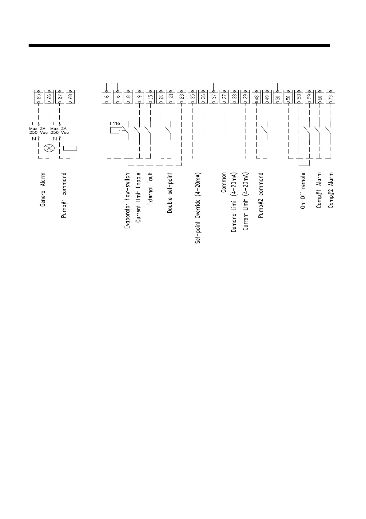
Field Wiring Diagram
Figure 17, Typical Field Wiring Diagram, Sheet 1
NOTE:
1 Compressor Alarm No. 3 applies to future product releases.
2 The compressor alarms will not be energized by a unit fault, only the unit alarm will do so. Using the unit
alarm and the circuit alarms will include all faults and also designate which compressor has an alarm.
3 Field wiring for optional BAS continued on next page.