Page 10 IM 781-2
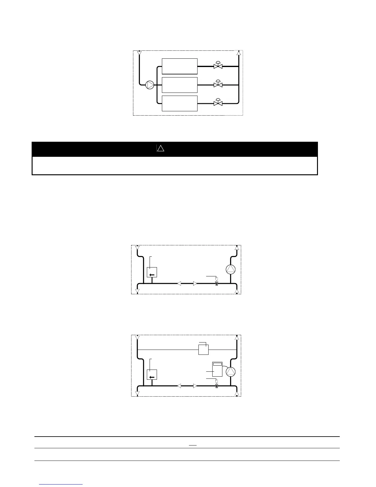
Figure 6. Common Primary Pump with Separate Isolation Valves
Chiller(s)
Chiller(s)
Chiller(s)
!
CAUTION
Significant changes in the chilled water flow rate through the evaporators can result when chillers in Figure 6 are
turned on or off. Large flow rate changes can cause erratic chiller control.
Secondary Pump/Decoupler Line Configuration
Figure 7 through Figure 10 represent the four secondary pump control options available using the CSM.
Figure 7. Fixed-Speed Secondary Pump
Decoupler line temperature
FM
Uni-directional flow meter
(supply to return)
a0100
Figure 8. Variable-Speed Secondary Pump
Note:
A pressure-controlled loop bypass may not be used with a
variable-speed secondary pump.
DPT
Differential pressure transducer
Decoupler line temperature
VFD
FM
Uni-directional flow meter
(supply to return)
Variable frequency drive
a0101
Using the variable-speed secondary pump maintains a desired pressure across the chilled water loop.
Note: A pressure-controlled loop bypass (see Figure 11) may not be used with variable-speed secondary pump(s).
 Loading...


