IM 781-2 Page 35
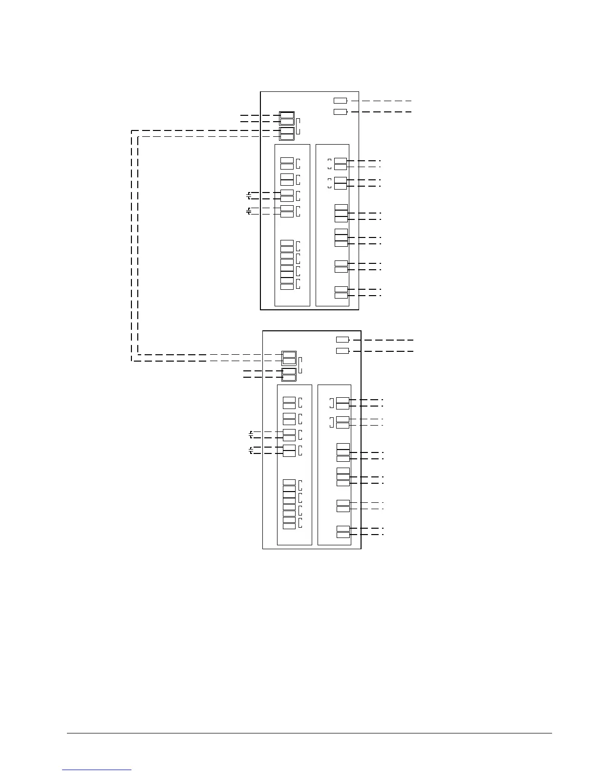
Figure 25. CSM Remote I/O Modules A and B Field Wiring Schematic
Remote A
Inputs
27 (Y)
26 (0)
DI 3
20 (Y)
19 (0)
17 (Y)
I6 (0)
14 (Y)
I3 (0)
11 (Y)
10 (0)
AI 4
AI 3
AI 2
AI 1
29 (Y)
28 (0)
DI 4
Lon Port
8 (Y)
7 (0)
DI 2
Cooling Load Pump 2 Enable
Outputs
NC 57
Com56
NO 58
NC 54
Com53
NO 55
Com49
NO 50
Com47
NO 48
Relay 5
Relay 4
Relay 2
Relay 1
4
3
Cooling Load Pump 1 Enable
35 (Y)
34 (0)
AO 2
32 (Y)
31 (0)
AO 1
Cooling Load Pump VFD Speed
24 Vac
0
24 Vac power
50/60 Hz
6 (Y)
5 (0)
DI 1
Cooling Load Pump VFD Speed
Cooling Load Pump 1 Status
(Flow Proving Device)
Cooling Load Pump 2 Status
(Flow Proving Device)
Remote B
Inputs
27 (Y)
26 (0)
DI 3
20 (Y)
19 (0)
17 (Y)
I6 (0)
14 (Y)
I3 (0)
11 (Y)
10 (0)
AI 4
AI 3
AI 2
AI 1
29 (Y)
28 (0)
DI 4
Lon Port
8 (Y)
7 (0)
DI 2
Cooling Load Pump 4 Enable
Outputs
NC 57
Com56
NO 58
NC 54
Com53
NO 55
Com49
NO 50
Com47
NO 48
Relay 5
Relay 4
Relay 2
Relay 1
4
3
Cooling Load Pump 3 Enable
35 (Y)
34 (0)
AO 2
32 (Y)
31 (0)
AO 1
Cooling Load Pump VFD Speed
24 Vac
0
24 Vac power
50/60 Hz
6 (Y)
5 (0)
DI 1
Cooling Load Pump VFD Speed
Lon Network to Chillers, CSM,
and/or other Remote I/O Modules
Notes: 1.
All remote I/O modules are optional. Their requirement is
based on the number of pumps, valves and/or cooling
tower fans controlled by the CSM.
0-10Vdc
0-10Vdc
-10Vdc
0-10Vdc
6A @ 230V
6A @ 230V
6A @ 230V
6A @ 230V
6A @ 230V
6A @ 230V
6A @ 230V
6A @ 230V
Cooling Load Pumps 1 and 2
Cooling Load Pumps 3 and 4
Lon Network to Chillers, CSM,
and/or other Remote I/O Modules
2
1
2
1
25
24
25
24
Cooling Load Pump 3 Status
(Flow Proving Device)
Cooling Load Pump 4 Status
(Flow Proving Device)
CD 251740501
 Loading...


