Page 14 of 36 / IM 985-1
Standard Range Geothermal Range
Units Units
Cooling
Heating Cooling Heating
Min. Entering. Water
55°F/13°C 55°F/13°C 30°F/-1°C 20°F/-6°C
Normal Entering. Water 85°F/29˚C 70˚F/21°C 77°F/25˚C 40˚F/5°C
Max. Entering. Water
1
10°F/43˚C 90°F/32°C 110°F/43˚C 90°F/32°C
At ARI flow rate.
Maximum and minimum values may not be combined. If one value
is at
maximum or minimum, the other two conditions may not exceed the
normal condition for standard units. Extended range units may combine any
two maximum or minimum conditions, but not more than two, with all other
conditions being normal conditions.
Table 5. Water Limits
Table 4. Air Limits
Standard Range Geothermal Range
Units Units
Cooling
Heating Cooling Heating
Min. Ambient Air 50˚F/10˚C 50˚F/10˚C 40˚F/5˚C 40˚F/5˚C
Normal Ambient Air 80˚F/27˚C 70˚F/21˚C 80˚F/27˚C 70˚F/21˚C
Max. Ambient Air 100˚F/38˚C 85˚F/29˚C 100˚F/38˚C 85˚F/29˚C
Min. Entering. Air
50˚F/10˚C
50˚F/10˚C 50˚F/10˚C 40˚F/5˚C
Normal Entering Air, 80˚F/67˚F 70˚F 80˚F/67˚F 70˚F
db/wb 27/19˚C 21˚C 27/19˚C 21˚C
Max. Entering Air 100/83˚F 80˚F 100/83˚F 80˚C
db/wb
38/28˚C
27˚C 38/28˚C 27˚C
Additional Information
Units are designed to start and operate with entering air
at 40°F (4°C), with entering water at 70°F (21°C), with
bothairandwaterattheowratesusedintheARI-
Standard 320-86 rating test, for initial start-up in winter.
Note: This is not a normal or continuous condition.
It is assumed that such a start-up is for the purpose
of bringing the building space to occupancy
temperature.
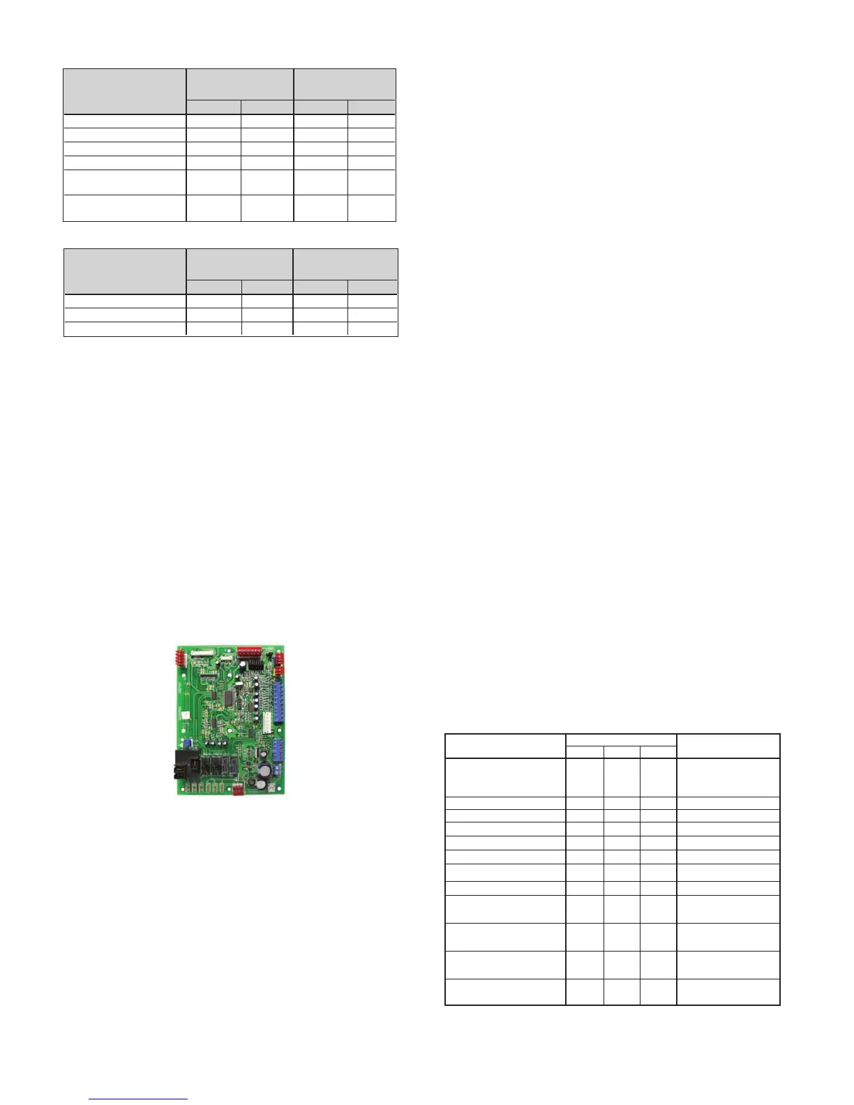
MicroTech® III Unit Controller
The MicroTech III Unit Controller includes built-in
features such as random start, compressor time delay,
shutdown,condensateoverowprotection,defrost
cycle, brownout, and LED/fault outputs. Table 6 shows
the LED and fault output sequences.
The unit has been designed for operation with either
a unit mounted thermostat or a microelectronic wall
thermostat, selected by the manufacturer. Do not operate
the unit with any other type of wall thermostat.
Each unit has a printed circuit board control system. The
low voltage output from the low voltage terminal strip
is AC voltage to the wall thermostat. R is A/C voltage
output to the wall stat.
The 24 volt low voltage terminal strip is set up so R-G
energizes the fan, R-Y1 energizes the compressor for
cooling operation, R-W1 energizes the compressor and
reversing valve for heating operation. The reversing
valve is energized in the heating mode. The circuit
board has a fan interlock circuit to energize the fan
whenever the compressor is on if the thermostat logic
fails to do so.
The output to the wall stat is AC current. Terminal (R)
on the wall stat can be connected to terminal (R) on the
PC board for AC voltage.
R
= AC current
R to G = fan only
R to Y1 = cooling
R to W1 = heat
The
MicroTech III unit controller has a lockout circuit
to stop compressor operation if any one of its safety
devices is triggered (high pressure switch and low
temperature sensor). If the low temperature sensor is
triggered, the unit will go into the cooling mode for 60
seconds to defrost any slush in the water-to-refrigerant
heat exchanger. After 60 seconds the compressor is
lockedout.Ifthecondensatesensordetectsalleddrain
pan, the compressor operation will be suspended only
in the cooling mode. The unit is reset by opening and
closing the disconnect switch on the main power supply
to the unit in the event the unit compressor operation
has been suspended due to low temperature sensor or
high pressure switch. The unit does not have to be reset
onacondensateoverowdetection.
The MicroTech III unit controller fault output sends a
signal to an LED on a wall thermostat. Table 6 shows
for which functions the fault output is “on” (sending a
signal to the LED).
Mode / Fault
Status LED’
s
Thermostat Alarm Light
Y
ellow Green Red Output-Terminal “A”
Occupied, Bypass,
Standby
, or Tenant Off On Off Energized
Override
Unoccupied On On Off Energized
Condensate Overow On Off Off De-engergized
High Pressure 1 Fault
Off Off Flash De-energized
Low Pressure 1 Fault Off Off On De-energized
Low Temperature 1 Fault Flash Off Off De-energized
Brownout
Off Flash Off De-energized
Emergency Shutdown
Off Flash Off De-energized
Room/Return
Air or Low
Flash Flash On De-engergized
Temp Sensor 1 Failure
Service Test Mode
On On Off De-energized
Enabled
1
Serial EEPROM
On On On De-energized
Corrupted
Network “Ofine”
Off Off Off De-enegized
Received
Table 6. MicroTech III Unit Controller LED & Fault Outputs
1
Compressor relay/compressor terminal is labeled COMP, switched line of the
same electric input as any of the L1 terminals.