IM 985-1 / Page 29 of 36
Note: Connectors on valve must be cut off and
stripped back and the wires twisted to make
connections to the IV/PR Terminals
Pump Restart Relay Kit P/N 061419001
The MicroTech III unit controller has an internal Pump
Restart Relay connected to H8, Pin 2 for the Normally
Open (N/O) terminal of the internal relay.
Connect to H8, Pin 1 for the Normally Closed (N/C)
terminal of the internal relay.
The output of the internal pump restart relay is 24-
volts AC and the output is not available when the H8
connection is used to control a motorized valve.
Multiple Unit Control Panel (MUCP) for Use With
MicroTech® III Unit Controller
For detailed installation instructions refer to IM 952
The Multiple Unit Control Panel (MUCP) is an
accessory used when up to 3-units are controlled from a
single thermostat. Console units must have the MUCP
eld-installedinaremotelocation,typicallyclosetothe
units and convenient for service access.
A maximum of 2 boards may be used together if up to
6-units must be connected and controlled from a single
thermostat.
Note: The MUCP control board does not t inside
the console unit control box.
Multi-speed operation is only available with the
optional unit-mounted fan speed switch.
T
he multiple unit control board provides the components
necessary to protect the MicroTech III unit controller
from electrical damage that may occur when using
standard off-the-shelf relays.
This version of the board uses VAC relays and should
not be used in combination with any other accessories
or equipment that require VDC connections to the “G”,
“W1”, or “Y1” terminals (i.e. Boilerless System Kit).
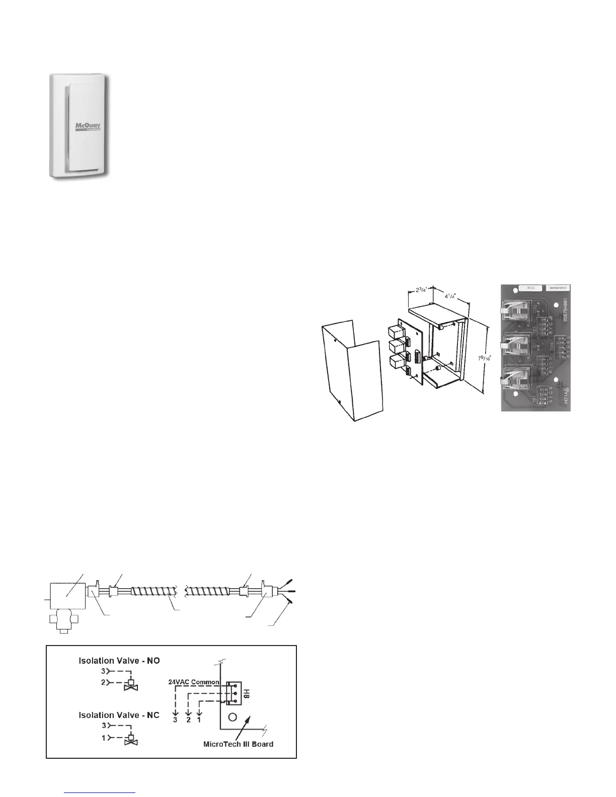
Optional Remote Sensor (P/N 66720401)
The fast, easy solution for temperature sensing problems.
•
For tamper prone areas
• Poor airow areas
• Troubled applications
• Foam gasket prevents drafts through
wall opening
• Mounts to standard 2" x 4" outlet box
• 2¾"W x 4½"H
1. Remove cover from remote
sensor housing.
2. Select an appropriate location for mounting the
remote sensor.
3. Mount remote sensor unit using hardware provided.
4. Install two strand shielded wire between remote
sensor and thermostat. Shielded wire must be used.
Do not run remote sensor wire in conduit with other wires.
• Wire 1 should run between the S1 terminal on the
thermostat and the S1 terminal on the remote sensor
• Wire 2 should run between the S2 terminal on the
thermostat and the S2 terminal on the remote sensor
• Connect the shielding of the wire to the S2 terminal
on the thermostat
5. Disable the main sensor (R12) on the thermostat by
cutting it from the circuit board.
Motorized Isolation Valve & Relay
Themotorizedvalvekitmaybeorderedasaeld-
installed accessory.
Wired as shown in Figure 23, the motorized valve will
open on a call for compressor operation. Valves for unit
sizes007to018are1/2".
Using a Normally Closed (N/C), power open valve,
wire as illustrated in Figure 23.
Figure 23. Normally Closed, Power Open Motorized Valve
Wiring
Actuator &
Valve Assembly
Anti-short Bushing
Connector
Conduit
Pin(s), female
plug into receptacle
Connector
Anti-short
Bushing