Page 4 of 36 / IM 985-1
Note: If using the Alternate Unit Installation procedure
(Using Mounting Brackets, page 6) it is not necessary
to remove the top section. Continue with step 5 if
using the recommended method of installation.
5
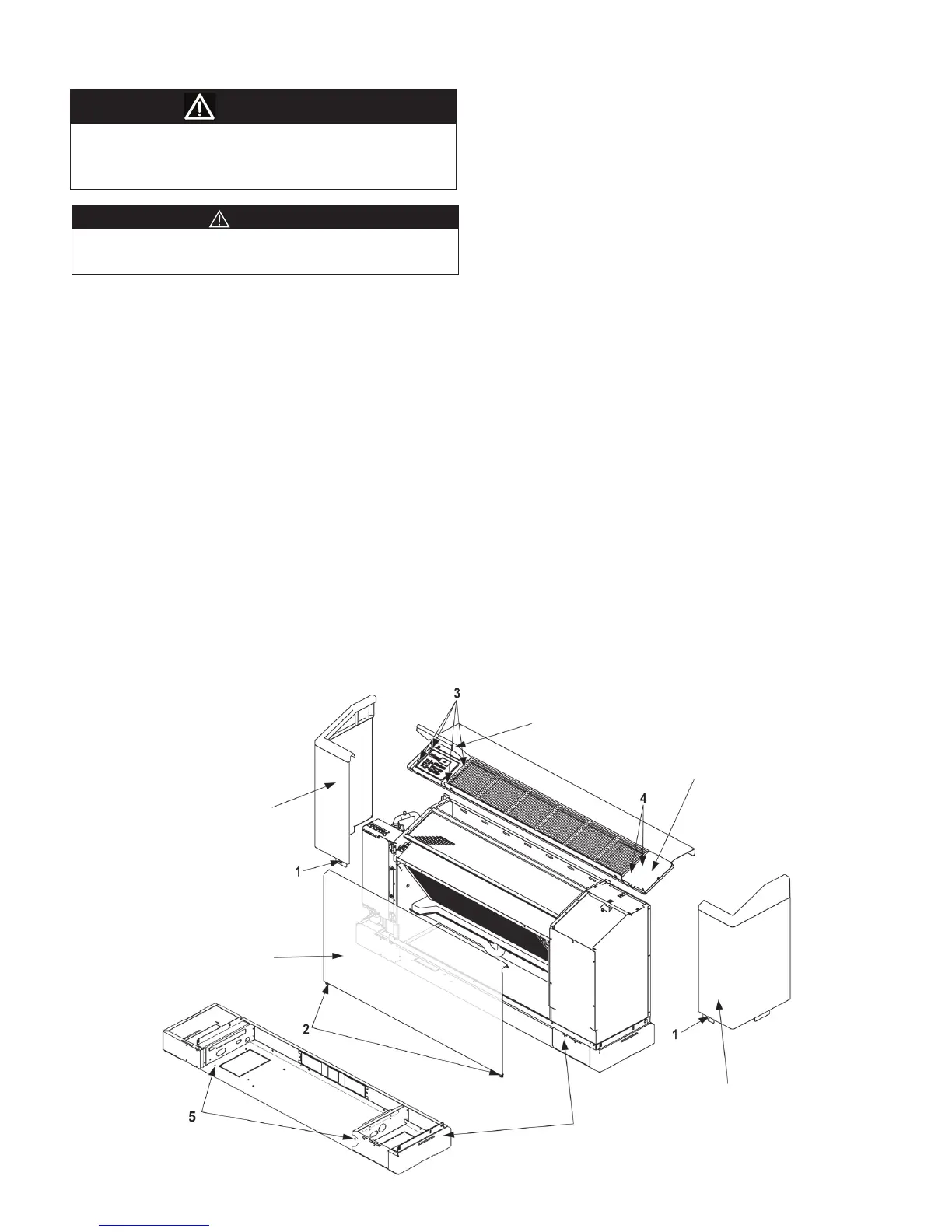
. Open the control door and remove the four screws
that hold the top panel and control pad in place
(numbered 3) in Figure 1. On the opposite end of the
cabinet top lift off the blank-off plate to the right and
remove the last two mounting screws (numbered 4)
in Figure 1. Lift the top panel off, turning the control
padsothatittsdownthroughtheopeninginthe
top panel.
Note: After removing the panels, set aside in a safe
area where they will not be damaged.
STOP! If an outside air damper kit is to be installed,
refer to IM 974 for the manual damper and the
motorized damper kit and install it now.
6
. Position the chassis/subbase against the wall where
the unit is to be installed. Remove any mouldings
attheoororwall(seeletterAinFigure2).Allow
adequate room for piping and electrical connections
in the subbase by checking the electrical connection
end of the subbase and chassis.
Note: Make sure electrical and piping connections
are in the proper location within the subbase end
piping compartment.
Unit Installation (Recommended)
Installation and maintenance are to be performed by
qualied personnel who are familiar with local codes and
Regulations, and experienced with this type of equipment.
1. Consult job blueprints for unit location. Clean area
where unit is to be installed, removing all
construction dirt and debris.
2. Remove the unit from the shipping carton and save
the carton to be used as a protective cover after the
installation is complete.
3. Remove the screws (numbered 1) shown in Figure
1, securing the right and left side /corner panels
to the subbase. Lift the panels up and out until the
bottom tab clears the slot in the subbase.
Note: Set the unit panels aside where they will not
be damaged.
4
. Remove the two screws (numbered 2) in Figure 1
securing the front panel to the subbase and remove
the panel by lifting up and tilting out until the panel
tabs clear the slots in the subbase.
Sharp edges can cause personal injury. Avoid contact
with them.
CAUTION
WARNING
Figure 1. Cabinet Panel Screw locations and Panel Removal
Right Corner Panel
Blockoff Plate
Subbase
Front Panel
Left Corner Panel
Control Door