IM 985-1 / Page 15 of 36
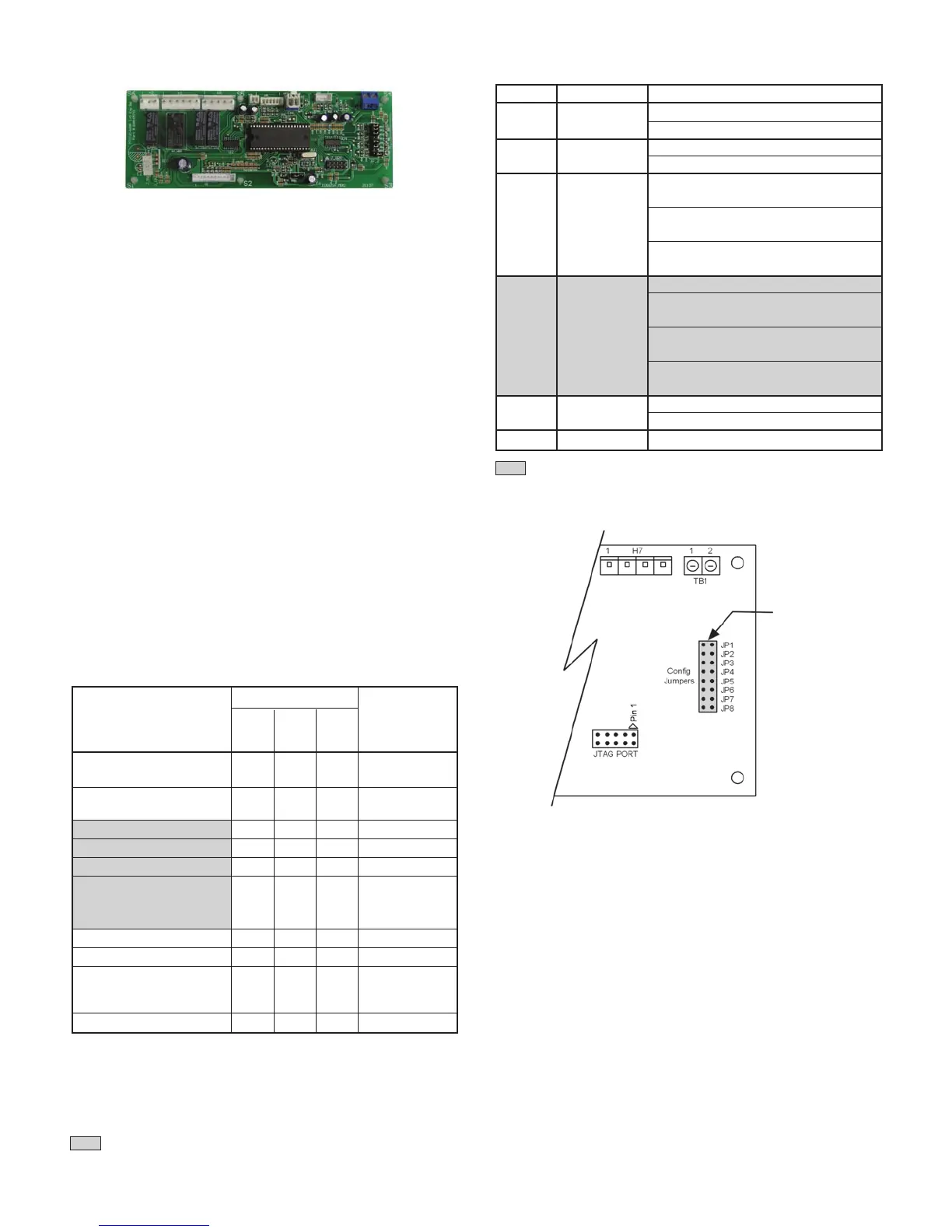
Figure 12. I/O Expansion Module Conguration Jumper Terminals
Adding an I/O Expansion Module (with an interconnect
cable) to the unit controller allows the operation of
boilerless electric heat with the Console Water Source
Heat Pump.
Features
Standard Heat Pumps / Single Circuit Units
• Monitors entering water temperature for
boilerless electric heat control
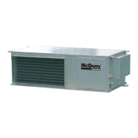
I/O Expansion Module
This manual covers the installation of a McQuay
Console Unit - Model MHC, MHW Water Source
Heat Pump. For installation and operation information
on MicroTech III unit controller and other ancillary
components, see:
• IM 927 - MicroTech III L
onWorks Communication
Module
•
IM 928 - MicroTech III BACnet Communication
Module
•
OM 931 - MicroTech III Unit Controller for Water
Source Heat Pumps Operation and Maintenance
Manual
The
I/O Expansion Module is a factory installed option.
It is an extension of the MicroTech III unit controller
and provides extra functionality.
The I/O Expansion Module has 2 main purposes:
• The I/O Expansion Module has outputs to control
electric heat on a standard Water Source Heat Pump.
• The I/O Expansion Module has an independent LED
annunciator to identify operational fault conditions
for the electric heater.
Table 7 . I/O Expansion Module LED & Fault Outputs
Jumper Description Options
JP1
Number of
Open for single compressor
Compressors Shorted for dual compressor
JP2
Hot Gas/
Open to disable reheat
Water Reheat Shorted to enable reheat
JP3 and JP4 open for no
supplemental heat
JP3
Supplemental JP3 open, JP4 shorted for
& JP4 Heat Type boilerless electric heat
JP3 and JP4 shorted is an
invalid setting
JP5 and JP6 open for single-speed fan
JP5 open, JP6 shorted for
JP5
Fan Speed three-speed fan
& JP6 Selection JP5 shorted and JP6 open for
two-speed fan
JP 5 and JP6 shorted is an
invalid setting
JP7
Compressor Open for single-speed compressor
Speed Type Shorted for two-speed compressor
JP8 Future Spare
Table 8. I/O Expansion Module Conguration Jumper Settings
1
Boilerless electric heat only
2
Alarm/fault LED indications take precedence over service test mode LED
indication. The controller shall use service test mode if the service test mode
jumper is installed, even if the LED’s indicate an alarm/fault.
Note: Mode / Faults are listed in order of priority.
Status LED's
Thermostat Alarm
Mode / Fault
Y
ellow Green Red
Light Output
Terminal “A”
Invalid Conguration
Flash Flash Off De-energized
Jumper Setting
Base Board
Off Flash Flash N/A
Communication Fail
High Pressure #2 Fault Off Off Flash De-energized
Low Pressure #2 Fault Off Off On De-energized
Low Suction Temp #2 Fault
Flash Off Off De-energized
Sensor Failures Low Suction
Low Suction
Temp #2, Flash Flash On De-energized
1
EWT (w/ Boilerless EH only)
2
Service Test Mode Enabled Flash Flash Flash De-energized
Unoccupied Mode On On Off Energized
Occupied, Bypass,
Standby, or Tenant
Off On Off Energized
Override Modes
Normal Operation
Off On Off De-energized
Jumper Terminals
= Not used with Console Water Source Heat Pump unit.
= Not used with Console Water Source Heat Pump unit.