IM 985-1 / Page 33 of 36
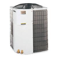
Figure 26. Cooling Mode
Return Air
Reversing Valve
Conditioned Air
(Cooling)
Thermal
Expansion Valve
Coaxial Heat
Exchanger
Blower
Coil – Air to Refrigerant
Heat Exchanger
Water In
Water Out
Sensing Bulb and
Capillary Tube
Compressor
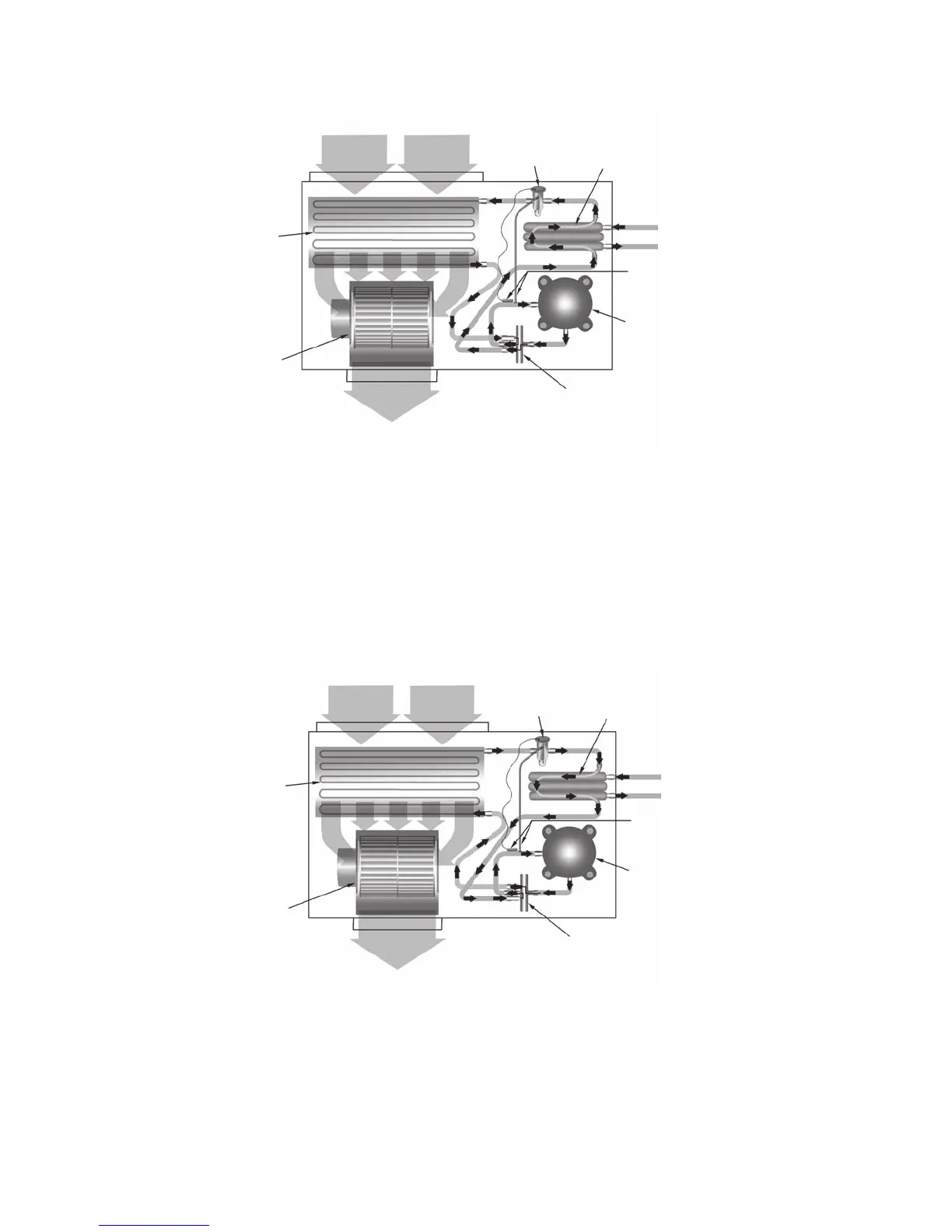
Figure 27. Heating Mode
Return Air
Thermal
Expansion Valve
Coaxial Heat
Exchanger
Reversing Valve
Conditioned Air
(Heating)
Blower
Water In
Water Out
Sensing Bulb
and Capillary Tube
Compressor
Coil – Air to Refrigerant
Heat Exchanger
Cooling Refrigeration Cycle
WhenthewallthermostatiscallingforCOOLING,thereversingvalvedirectstheowoftherefrigerant,ahotgas,
leaving the compressor, to the water-to-refrigerant heat exchanger. Here the heat is removed by the water and the
hotgascondensestobecomealiquid.Theliquidthenowsthroughathermalexpansionmeteringsystemtothe
air-to-refrigerant heat exchanger coil. The liquid then evaporates becoming a gas, at the same time absorbing heat
andcoolingtheairpassingoverthesurfacesofthecoil.Therefrigerantthenowsasalowpressuregasthroughthe
reversing valve and back to the suction side of the compressor to complete the cycle.
Heating Refrigeration Cycle
WhenthewallthermostatiscallingforHEATING,thereversingvalvedirectstheowoftherefrigerant,ahotgas,
leaving the compressor, to the air-to-refrigerant heat exchanger coil. Here the heat is removed by the air passing
overthesurfacesofthecoilandthehotgascondensestobecomealiquid.Theliquidthenowsthroughacapillary
thermal expansion metering system to the water-to-refrigerant heat exchanger. The liquid then evaporates becoming
agas,atthesametimeabsorbingheatandcoolingthewater.Therefrigerantthenowsasalowpressuregasthrough
the reversing valve and back to the suction side of the compressor to complete the cycle.
Typical Cooling and Heating Refrigeration Cycles
 Loading...