IM 985-1 / Page 35 of 36
Troubleshooting the MicroTech III
Unit Controller
General Use and Information
The Microtech III unit controller is provided with two
drive terminals, R(24VAC) and C(0 VAC) that can be
used by the end user to drive the thermostat inputs (G,
Y1, Y2, W1, and W2) and control inputs (U, E, and
O). Any combination of a single board drive terminal
(R or C) may be used to operate the MicroTech III unit
controller’s control or thermostat inputs. However, only
one drive terminal (R or C) can be connected to any
individual input terminal or damage may result. Some
control inputs are not accessible to the end user (for
example, HP, LP, SLTS, and COF).
Typically the Microtech III unit controller’s R (24VAC)
terminal is used to drive the board’s thermostat inputs
and control inputs by connecting it to the R terminal
of an industry standard thermostat. The control outputs
of the standard thermostat are then connected to the
Microtech III unit controller thermostat inputs and
control inputs as needed. Any remaining board input(s)
may be operated by additional thermostat outputs or
remote relays (dry contacts only).
All Microtech III unit controller inputs must be operated
by dry contacts powered by the control board’s power
terminals. No solid state devices (Triacs) may be used
to operate the Microtech III unit controller inputs.
No outside power source may be used to operate the
Microtech III unit controller inputs.
To avoid electrical shock, personal injury or death, be
sure that field wiring complies with local and national fire,
safety, and electrical codes, and voltage to the system is
within the limits shown in the job-specific drawings and
unit electrical data plate(s).
Power supply to unit must be disconnected when
making field connections. To avoid electrical shock, per-
sonal injury or death, be sure to rigorously adhere to field
wiring procedures regarding proper lockout and tagout of
components.
DANGER
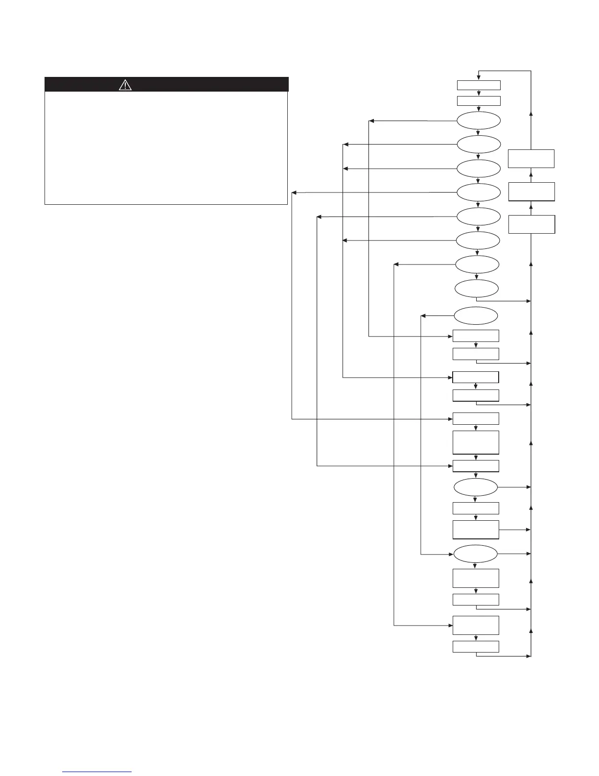
Figure 29. MicroTech III Unit Controller LED Status and Faults
Troubleshooting Reference
Flash Yellow LED
Read Outputs
Check Timers
Brownout
High
Pressure
R - W 1
R -Y 1
Flash Green LED
Stop Compressor
No
Yes
No
No
No
No
No
No
No
No
Yes
Yes
Yes
Yes
Yes
Yes
Yes
Yes
Low
Pressure
Low Suct
Temp Sensor
Low Suct
Temp
Room Temp
Sensor Failure
Condensate
Overflow
Stop Compressor
Flash Red LED
Stop Compressor
Flash Yellow LED
Flash Green LED
Solid Red LED
Stop Compressor
Heating Mode
Run in Cooling
Mode for 1 Min.
No
Yes
Cooling Mode
Turn on
Yellow LED
Stop Compressor
Reversing
Valve On
Time Delay
Start
Compressor
30 Second
Time Delay
Request for
Water Flow
 Loading...