IM 985-1 / Page 5 of 36
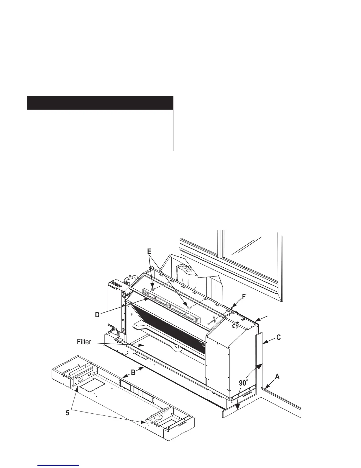
Figure 2. Unit Mounting Details
7. Removethelterandlocatetheexisting1/4"
mounting holes in the bottom of the subbase labeled
(5) in Figure 2 subbase detail.
8. Be sure the subbase is tight to the wall. Transfer
amarkwithamarkerorpenciltotheoorat
mounting hole locations (5).
9. Moveunitawaytopre-drill1/4"mountingholesin
theooratmarkedlocations.
Clean unit mounting area of all construction debris. Check
that the floor is level and at 90 degrees to the wall as
shown in Figure 2.
McQuay recommends the placement of a sound absorbing
mat beneath the unit footprint before continuing to the next
installation step.
Note: Use the appropriate fasteners by others in
accordance with local building codes.
10. Insert fasteners through the mounting holes in
thesubbaseandsecurethesubbasetotheoor,
tightening the fasteners. Do not over-tighten
fasteners and distort or warp the subbase plate.
IMPORTANT
11. Use a carpenters square and level to check that the
unitisleveland90-degreestothewallandoor(see
letters C & D in Figure 2).
12. The chassis back panel has a series of slots on the
backangetomounttheassemblytothewall.Itis
the installing contractor’s responsibility to select the
correct fasteners for each unit to meet local codes
(see letter E in Figure 2).
Note: Use a minimum of three fasteners to secure
the unit (eld supplied). Secure two fasteners into
wall studs.
At location(s) where no stud is present, secure with
a Toggle bolt or equivalent (by others) (see letter F
in Figure 2).
13
. Reinstall the panels in reverse order as performed in
steps 3 through 5 on page 4.
14. Cut out one side and the bottom of the shipping
carton, leaving the top and three sides to place over
the unit for protection during construction.