Page 6 of 36 / IM 985-1
Note: Use the appropriate fasteners by others in
accordance with local building codes.
STOP! If an outside air damper kit is to be installed,
refer to IM 974 for the manual damper and the
motorized damper kit and install it now.
6
. Insert fasteners through the mounting holes in
thesubbaseandnishsecuringtheunittothe
oor,tighteningthefasteners.Donotover-tighten
fasteners and distort or warp the subbase plate.
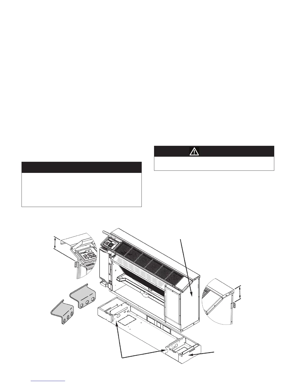
7. Locate mounting brackets at locations at the wall as
shown in Figure 3.
Note: Brackets should be located approximately 3"
from the top of the chassis, or lower if clearance is
necessary to fasten bracket.
8
. Mark the position of the bracket mounting holes
onto the wall. Remove the brackets and using a pre-
set depth drill, pre-drill holes to accept a wall anchor
(by others).
Failure to use a pre-set depth drill could result in serious
injury or death.
Note: It is preferred that the brackets are screwed
directly into a stud where available. However,
drywall anchors can be utilized when studs are
absent at bracket locations. It is the responsibility of
the installing contractor to provide the appropriate
fasteners and anchors to ensure that the unit is
secured properly.
WARNING
Left End View
Right End View
Provided Mounting
Brackets
Subbase
Chassis
(Shown removed from subbase for clarity)
Approximately 3"
5
Alternate Unit Installation
(Using Provided Brackets)
Procedure
1. With the front, left and right cabinet panels
removed,settheentireunitinitsnalmounting
position.
2. With the chassis still mounted on the subbase,
removeltertoallowaccesstothesubbasebottom
plate.
3. Locatetheexisting1/4"mountingholesinthe
bottom of the subbase labeled (5) in Figure 3.
Note: Make sure electrical and piping connections
are in the proper location within the subbase end
piping compartment.
4.
Transferamarkwithamarkerorpenciltotheoor
at mounting hole locations (5).
5. Moveunitawaytopre-drill1/4"mountingholesin
theooratmarkedlocations.
Clean unit mounting area of all construction debris. Check
that the floor is level and at 90 degrees to the wall as
shown in Figure 2, page 5
McQuay recommends the placement of a sound absorbing
mat beneath the unit footprint before continuing to the next
installation step.
IMPORTANT
Figure 3. Mounting Bracket Installation
 Loading...