IM 985-1 / Page 21 of 36
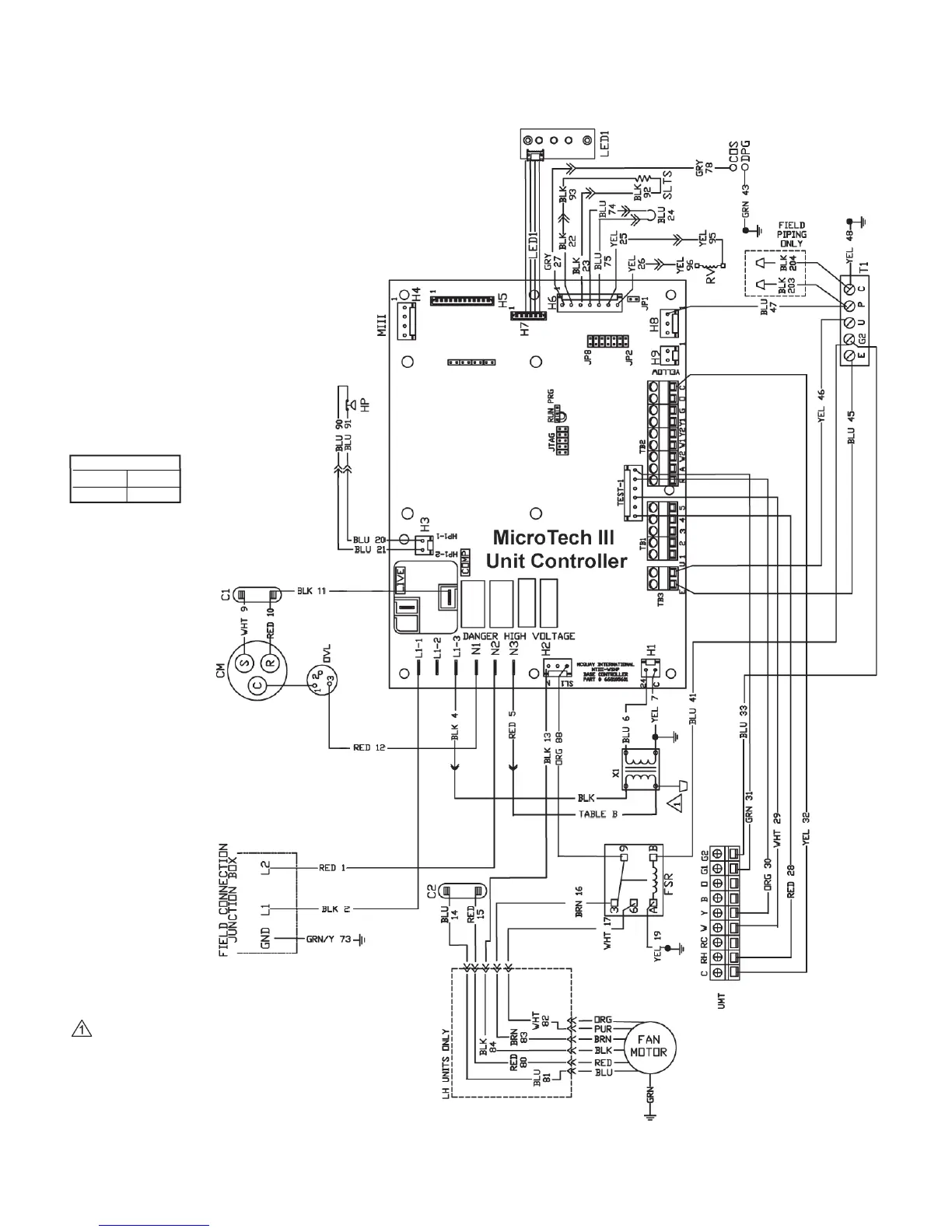
Typical Wiring Diagrams
MicroTech III Unit Controller for Sizes 007-015 – 208/230/60Hz/1-Phase
Notes:
Transformer:
Unused wire to be capped.
2. Unit wired for 208V, see Table “B”
T
able B
208V RED
230V ORG
Drawing No. 669539003A
Note: Wiring diagrams are typical. For the latest drawing version
refer to the wiring diagram located on the inside of the controls
access panel of the unit.
Legend
Item Description
C1 Capacitor-Compressor
C2 Capacitor-Fan
UMT Unit-Mounted Thermostat
CM Compressor - Motor
COS Condensate Overow Sensor
DPG Drain Pan Ground
FSR Fan Speed Relay
HP High Pressure Switch
SLTS Suction Line Temp Sensor
OVL Compressor Overload Protector
RV Reversing Valve Solenoid
T1 EG2UPC Terminal Strip
X1 Transformer
LED1 LED Annunciator / Harness
 Loading...