IM 985-1 / Page 23 of 36
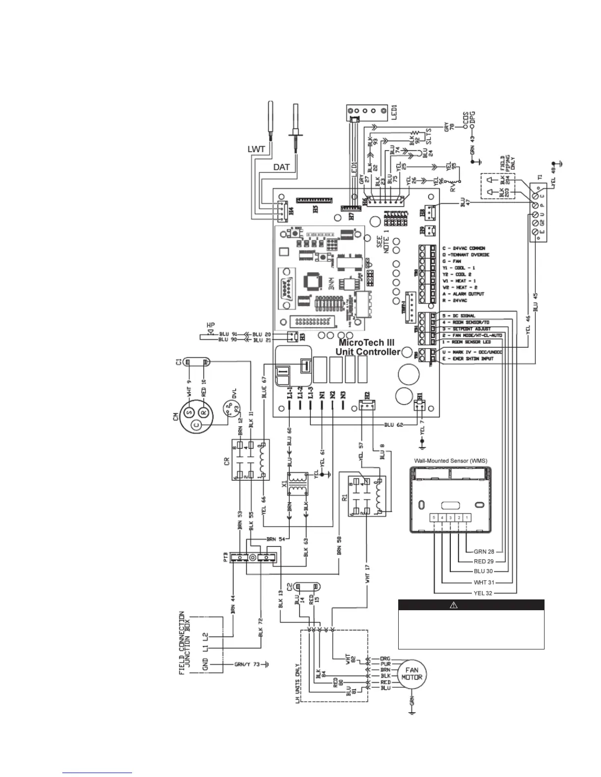
Typical Wiring Diagrams
MicroTech III Unit Controller with Communication Module and Wall-Mounted Room
Temperature Sensor
265/277/60Hz/1-Phase
Note: Wiring diagrams are typical. For the latest drawing version
refer to the wiring diagram located on the inside of the controls
access panel of the unit.
Legend
Item Description
C1 Capacitor-Compressor
C2 Capacitor-Fan
R1 Relay - Fan Motor
CM Compressor - Motor
COS Condensate Overow Sensor
DPG Drain Pan Ground
FSR Fan Speed Relay
PTB Power Terminal Block
HP High Pressure Switch
SLTS Suction Line Temp Sensor
OVL Compressor Overload Protector
RV Reversing Valve Solenoid
T1 EG2UCP Terminal Strip
X1 Transformer
LED1 LED Annunciator / Harness
CR Compressor Relay
LWT Leaving Water Temperature Sensor
DAT Discharge Air Temperature Sensor
Drawing No. 669542001
When the optional wall-mounted room temperature sen-
sor is connected to the unit controller, the Return Air
Temperature (RAT) sensor must not be installed. The wall-
mounted room temperature sensor and return air sensor
must not be connected simultaneously or the unit will not
operate properly.
CAUTION
 Loading...