42 IM710
MCB LED Power-Up Sequence
The various LEDs on the MCB are shown in Figure 25.
When power is applied to the MCB the LEDs on the board
should execute a specific startup sequence. This startup
sequence consists of 3 main components: LED Operational
Check period, the MCB Error Code Display period and the
MCB Initialization period. These are described in the fol-
lowing sections.
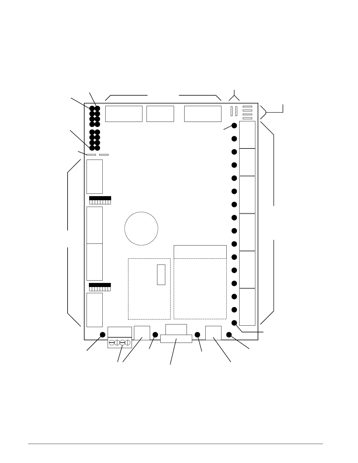
Figure 21: Main Control Board
........
........
................
......... ......... ......... ......... ...... ......
::::::::::::::::::::
BI-1
BI-8
BI-16
BI-9
BATTERY
......... ...............
SW-1
SW-4
BACnet ETHERNET
COMM. CARD
(OPTIONAL)
MOD-DCU
CONTROL BOARD
N2 BUS
PORT
ANALOG
INPUTS
RS-232
PORT
ETHERNET
PORT
BINARY
INPUTS
24VAC INPUT
POWER
ANALOG
OR
BINARY
OUTPUTS
BO-16
BO-1
ERROR
LED
24VAC
ISOLATION
POWER FOR
AO/BOs
+15VDC
POWER
FOR AIs
N2
ACTIVITY
LED
RS-232
ACTIVITY
LED
ETHERNET
ACTIVITY LED
BACnet MSTP
or LonMark
COMM. CARD
(OPTIONAL)
::::::
 Loading...


