IM 934-2 Applied PDAA/PDHA / Page 36 of 44
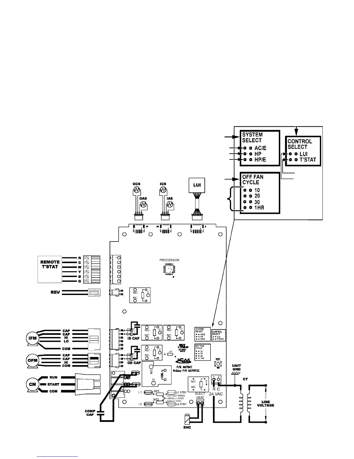
Standard (Non-programmable)
Digital Contol Wiring Diagram
3– Jumper Placement to Select
Controller Type:
A– Place jumper across LUI to select unit mounted
touchpad (Local User Interface).
B–
Place jumper across T’STAT to select
remote, wall mounted programmable, or non-
programmable thermostat.
3
2
1
Jumper Placement Detail
C
A
B
A
B
A
Wiring Diagram Legend
CT = Control Transformer
CM = Compressor Motor
IFM = Indoor Fan Motor
OFM = Outdoor Fan Motor
OCS = Outdoor Coil Sensor
OAS = Outdoor Air Sensor
ICS = Indoor Coil Sensor
IAS = Indoor Air Sensor
LUI = Local User Interface
REV = Reversing Valve
EHC = Eletric Heat Contactor
1– Jumper Placement to Select
System Module (See Jumper Detail)
A– Place jumper across AC/E to select Air Conditioner
with Electric Heat.
B–
Place jumper across HP to select Heat Pump.
C–
Place jumper across HP/E to select Heat Pump
with Electric Back-up Heat.
2– Jumper Placement to Select Fan Control
A– When in Fan Cycle Mode, fan operates for 2
minutes – Place jumper across 10, 20,
30, or 1 HR to select fan cycle off minutes which
will be overridden by the room temperature.