1-6
English
Model 5AC020CR 5AC025CR
Voltage Range ** 220 ~ 240V /1Ph /50Hz + N + !
Recommended Fuse * A 27 38
Power Supply Cable Size * mm
2
10 10
Number of Conductor 3 3
Interconnection Cable Size * mm
2
1.5 1.5
Cooling / Heat Pump
RECOMMENDED FUSE AND CABLE SIZES
IMPORTANT : * The figures shown in the table are for information purpose only. They should be checked and selected to
comply with the local/national codes of regulations. This is also subjected to the type of installation and
conductors used.
** The appropriate voltage range should be checked with label data on the unit.
!!
!!
! CAUTION
• All field wiring must be installed in accordance with the national wiring regulation.
• All the terminals and connections must be tightened. Improper connection and fastenings could cause electric shock,
short circuit and fire.
• Ensure that the rated voltage of the unit corresponds to that of the name plate before commencing wiring work
according to the wiring diagram.
• The unit must be GROUNDED to prevent possible hazards due to insulation failure.
• All electrical wiring must not touch the refrigerant piping, compressor, pump, fan motor or any moving parts of
the fan motors.
• Do not operate the chiller with wet hands. It would result in electric shock.
• Do not use fuse of different amperage than stated. Using wire etc. to replace a fuse could cause equipment damage
or fire.
P
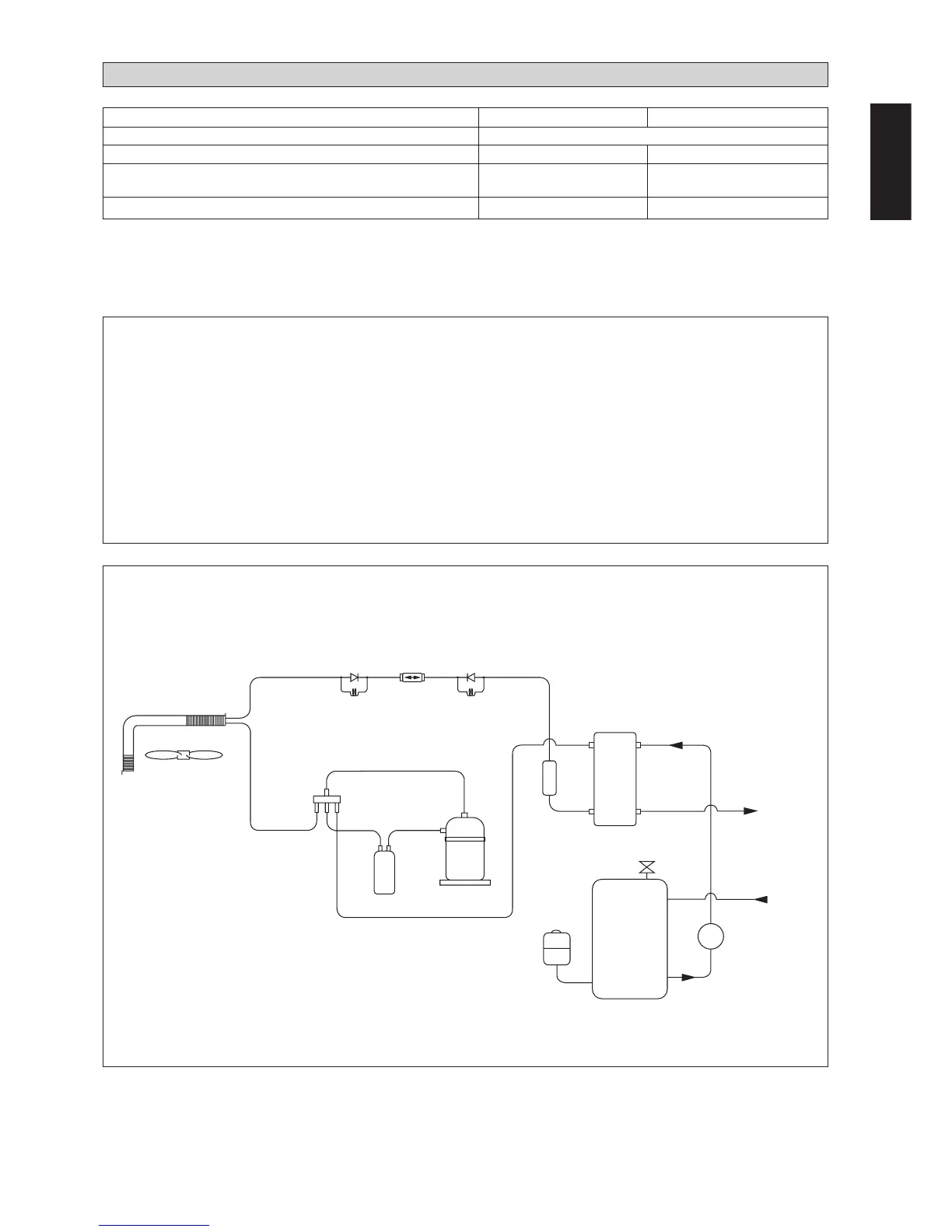
5AC 020/025 CR
Water / Refrigerant Circuit Diagram
CHECK
VALVE
BPHE
COMPRESSOR
CHARGE
COMPENSATOR
AUTO AIR VENT
WATER
OUT
WATER
IN
EXPANSION
TANK
WATER STORAGE
TANK
CHECK
VALVE
FILTER
DRIER
HEATING
CAP
TUBE
COOLING
CAP
TUBE
SUCTION
ACCUMULATOR
Figure 6
PART NO : 70-03-4-080547
WATER PUMP
 Loading...