1-5
P
WATER PIPING AND FITTING
• All water pipe must be adequately insulated to prevent capacity losses and condensation.
• Install a 40 to 60-mesh strainer to ensure good water quality.
• Water pipes recommended are black steel pipe and copper pipe.
• During installation, the piping of the unit should be clamped before rotating the installation pipe to reduce the moment
induce on the piping.
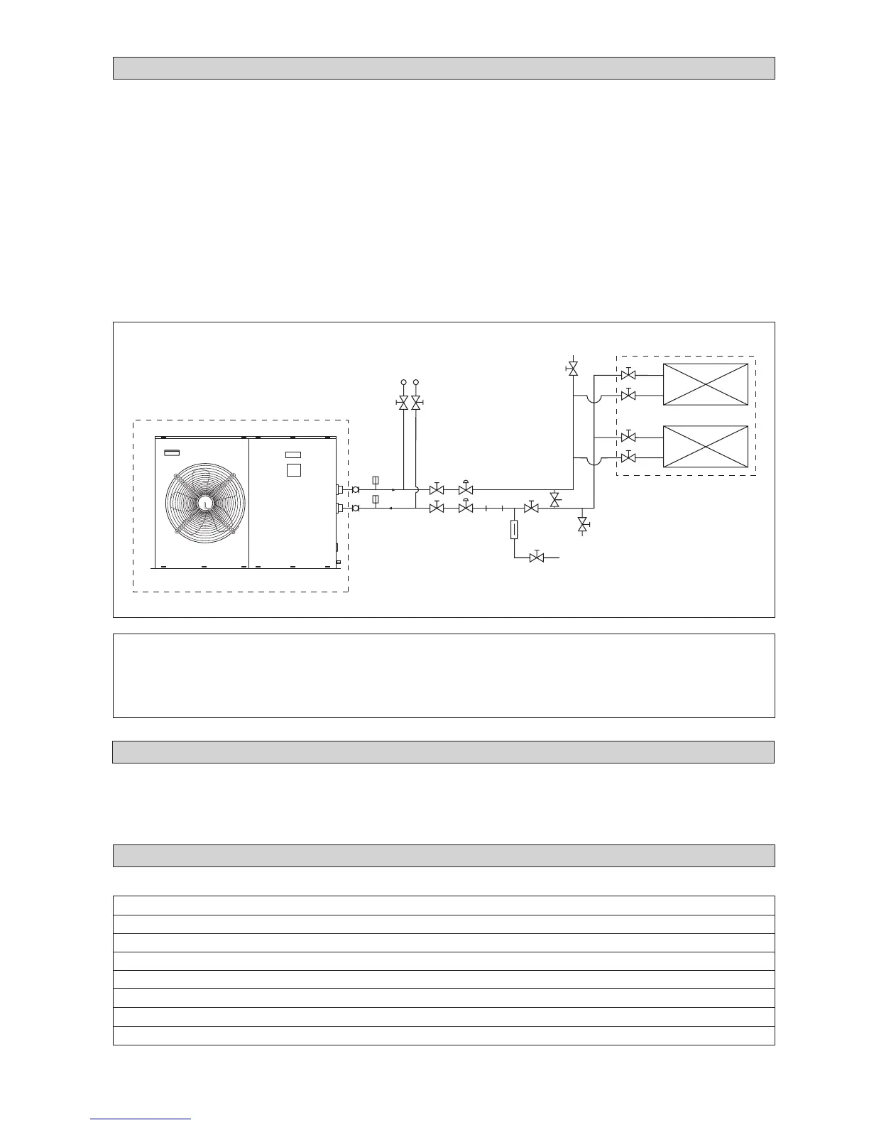
• Users are recommended to install the pipes and accessories as shown in Figure 5.
• An air vent must be installed at the highest position, while a drainage plug at the lowest position of the water circuit. After
the leak test (0.6MPa), open the air vent to release any air trapped in the water circuit.
• Run the clean water through the water inlet and operate the pump to drain out the dirty water. Clean the strainer after
running the pump for 30 minutes.
• Fill up the water circuit after connecting the pipes and equipment. Check water leakage at all connections and joints. Do
not start the unit when the system is leaking.
• To optimize the capacity of the system, ensure that the system is free of air bubbles. The air trapped in the system would
make the system unbalanced.
!!
!!
! CAUTION
• Do not allow water to remain in the water pipes if the unit is not operating for a long period.
Water must be drained out if the unit is not running during winter. Failing to do so would cause the pipe to crack.
• Do not drink the chilled water in the unit.
5AC 020/025 CR
PRESSURE GAUGE
GATE
VALVE
GATE
VALVE
BALANCING
VALVE
THERMOMETER
FLEXIBLE
GATE VALVE (LOWER
POSITION FOR DRAINAGE)
AIRVENT (INSTALL
HIGHEST POSITION)
FAN COIL UNIT/AIR HANDLING UNIT
GATE
VALVE
Figure 5
THERMO-
METER
GATE VALVE GATE VALVE
BALANCING
VALVE
STRAINER
CHECK
VALVE
BYPASS VALVE
(DIFFER ENT PRESSURE TYPE)
ELECTRICAL AND WIRING
• Refer to the wiring diagram provided on the unit when making electrical wiring.
• Do not ground any electrical equipment to the water piping.
• Install an external isolator switch (if it is not provided) to prevent electrical shock.
ELECTRICAL DATA
Table B-1 : ( R410A - Heatpump )
Model 5AC020CR 5AC025CR
Power supply V-ph-Hz 230 / 1 / 50
Voltage range V 220 - 240
Nominal Power Input (Cooling/Heating) kW 2.55/2.59 2.76/2.79
Nominal Current Input (Cooling/Heating) A 11.9/12.1 12.7/12.9
Maximum Starting Current A67 68
Pump Power Input (Cooling/Heating) W 185/193 195/209
Full Load Current (FLA) A14 15
MAKE UP
VALVE
 Loading...