IM 1068 / Page 11 of 32
A D F G H
in.
59
1
⁄
2
46
1
⁄
4
27
3
⁄
8
15
7
⁄
8
29
1
⁄
2
mm 1511 1175 695 403 749
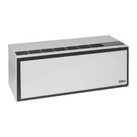
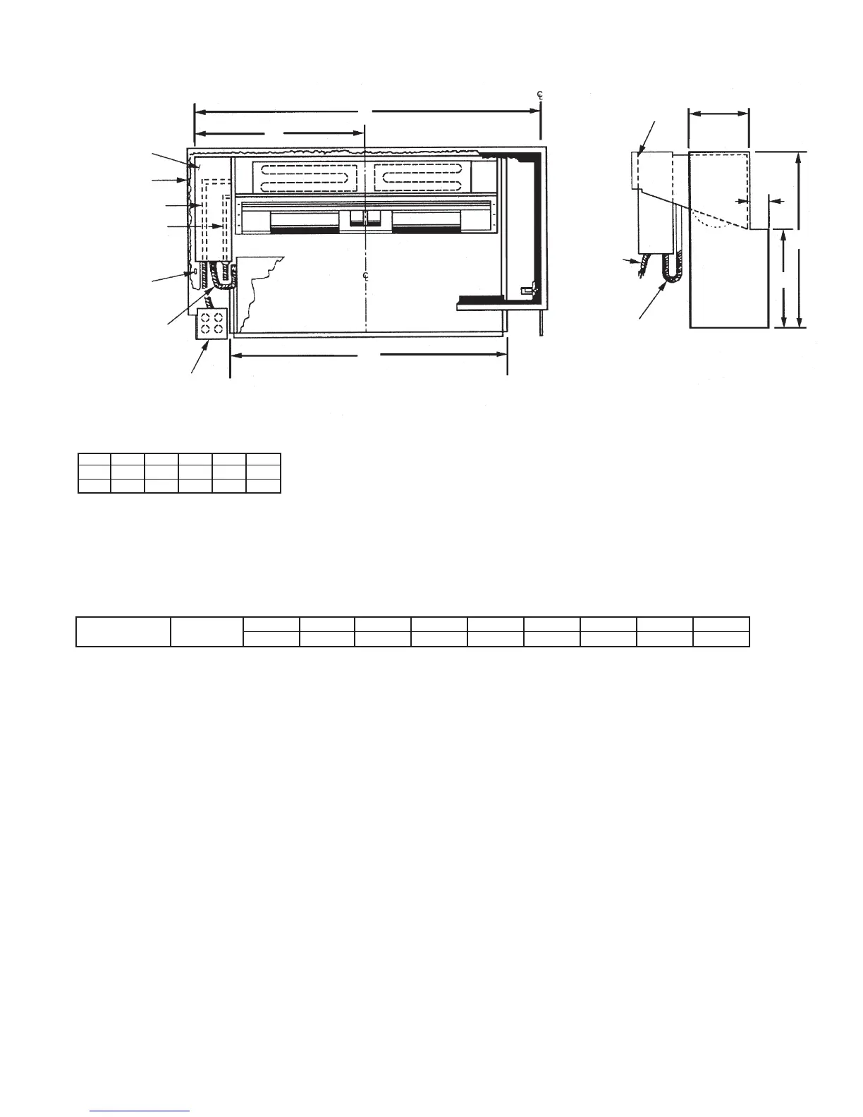
Front View
Side View
Room
Cabinet
Mounting
Holes (4)
Control Box
Room Cabinet
Main Power Cord
Heat Chassis
Power Cord
Cool Chassis
Power Cord
4" x 4" Junction Box
(Mounted by Others)
Field Mounted to L.H. Edge of Wall Box
Long
Control Box
Cool
Chassis
Power
Cord
Heat Section
Power Cord
Wall Box
(End View
w/o Cabinet)
B
A
H
D
F
G
9
1
/
4
"
(203 mm)
Figure 13: Electric Heat Section (Size 019)
Notes:
Guest room control, low voltage or master-slave wiring connection made at
control box.
See Table 7 for dimension B.
Table 6: Electric Heat Section Dimensions
Table 7: Wall Box “B” Dimensions
Wall Box Size 2
1
⁄
2
" 3
1
⁄
2
"
4" 5" 6" 7" 8" 9" 10"
“B” Dimension 019 64 mm 89 mm 102 mm 127 mm 152 mm 178 mm 203 mm 229 mm 254 mm
 Loading...