IM 1068 / Page 13 of 32
Notes:
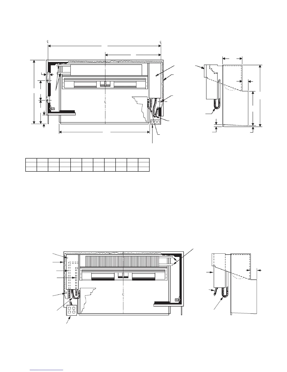
RefertoTable7onpage11for“B”dimension.
Front View
Side View
Room
Cabinet
Mounting
Holes (4)
Control Box
Room Cabinet
Main Power Cord
Heat Chassis
Power Cord
Cool Chassis
Power Cord
4" x 4" Junction Box
(Mounted by Others)
Field Mounted to L.H. Edge of Wall Box
Coil Stubs for Field Piping
Long
Control
Box
Cool
Chassis
Power
Cord
Heat Chassis
Power Cord
Wall Box
(End View
w/o Cabinet)
B
A D E F G H J K L M
in.
45
3
⁄
4
37 25
1
⁄
2
24
1
⁄
2
13
11
⁄
16
22
7
⁄
8
10 16 4
1
⁄
2
1
1
⁄
2
mm 1162 940 648 622 348 581 254 406 114 38
Notes:
See details G and H on page 7 for dimensions of factory installed valve and return piping stub.
See Table 9 on page 12 for dimension B.
The long control box is used with optional special controls such as Guest Room Control (GRC), Night Setback (NSB), and remote
thermostats.
Note: Left-hand piping must be used with the long control box design.
Side View
Room Cabinet Removed
Front View
8"
(203mm)
Long
Control Box
Room
Cabinet
Room Cabinet
Mounting Holes (4)
1
⁄
2
''
(12mm)
1
⁄
4
'' (6mm)
B
F
G
Cool Chassis
Power Cord
Heat Chassis
Power Cord
Flexible Conduit
Power Supply Cord
Junction Box (By Others)
H
A
M
J
K
L
D
Wall Box
Hydronic Coil
E
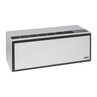
Figure 15: Hydronic Heat Section with Long Control Box (Sizes 007-012)
Table 10: Hydronic Heat Section with Long Control Box Dimensions
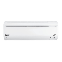
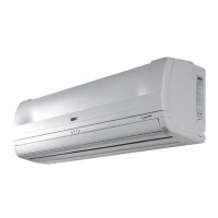
Figure 16: Units with Hydronic Heat (Size 019)
Unit with Hydronic Heat (size 019)
1. Only one size control box is available for size 019.
Make all electrical connections to a factory supplied
junction box located on the L.H. side of the wall box
(Figure 16).
 Loading...