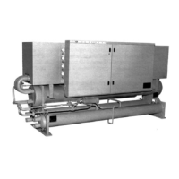
Product Manual WHR-2 77
2.04 CHILLER COMPONENTS
A. Compressors: The compressors shall be accessible hermetic reciprocating type
with suction and discharge service valves, crankcase oil heaters and suction
strainers. The compressors shall have a forced feed lubrication system with a
reversible oil pump, oil sight glass, and oil charge. The compressor motors shall
be refrigerant gas cooled, high torque, hermetic induction type, four-pole, with
inherent thermal protection on all three phases and shall be mounted on rubber
vibration isolators.
B. Evaporator: The evaporator shall be direct expansion type with steel shell,
polypropylene water baffles, and internally finned copper tubes roller expanded
into carbon steel tube sheets. Refrigerant heads shall be removable. The cooler
shall be insulated with 3/4 inch (12.7mm) closed cell insulation and painted with
resilient paint to resist cracking. It shall be designed, tested and stamped in
accordance with ASME Code requirements and have a 175 psi (1206 kPa)
maximum water side working pressure.
C. Condensers: Horizontal shell and finned tube type with steel shell and integral
finned copper tubes rolled into steel tube sheets which are to be drilled, and
multiple grooved to facilitate gas-tight rolling. The chiller shall be equipped with
intermediate tube supports. Construct condenser in accordance with the
requirements of ASME Section VIII Unfired Pressure Vessel Code and ANSI B9.1
Safety Code. It shall be designed for 225 psi (1550 kPa) water side working
pressure and 450 psig (3104 kPa) refrigerant side pressure and be provided with
ASME, ANSI B9.1 pressure relief valves.
D. Refrigerant Circuit: Each refrigerant circuit shall include a liquid line shutoff valve,
replaceable core filter-drier, sight glass with moisture indicator, liquid line
solenoid valve (no exceptions), thermal expansion valve, and insulated suction
line. The discharge line shall be equipped with a discharge muffler.
E. Control System: A centrally located control panel shall contain the field power
connection points, control interlock terminals, and control system. Power and
starting components shall include, fused control circuit with transformer, a motor
contactor, solid-state start timer, solid-state compressor three-phase motor
overload protection, and unit power terminal blocks for connection to remote
disconnect switch. Hinged access doors shall be lockable. Deadfront panels are
required to protect against accidental contact with line voltage when accessing
the control system.
Safety and operating control shall include unit control stop switch, recycling
pumpdown control, oil safety switch, high and low pressure safety switch, water
temperature controller, freeze protection pressurestat. The unit shall unload each
refrigerant circuit alternately. Unit shall provide recycling pumpdown protection
at all times.
--OR--
E. Microprocessor based control system: A centrally located control panel shall
contain the field power connection points, control interlock terminals, and control
system. Power and starting components shall include factory control
transformer, fusing of control circuit, solid-state start timer, solid-state
compressor three-phase motor overload protection, and unit power terminal
blocks for connection to remote disconnect switch. Hinged access doors shall be
lockable. Deadfront panels are required to protect against accidental contact with
line voltage when accessing the control system.

 Loading...