MDS 05-3316A01, Rev. E MDS 4710B/9710B I/O Guide 5
2.0 INSTALLATION
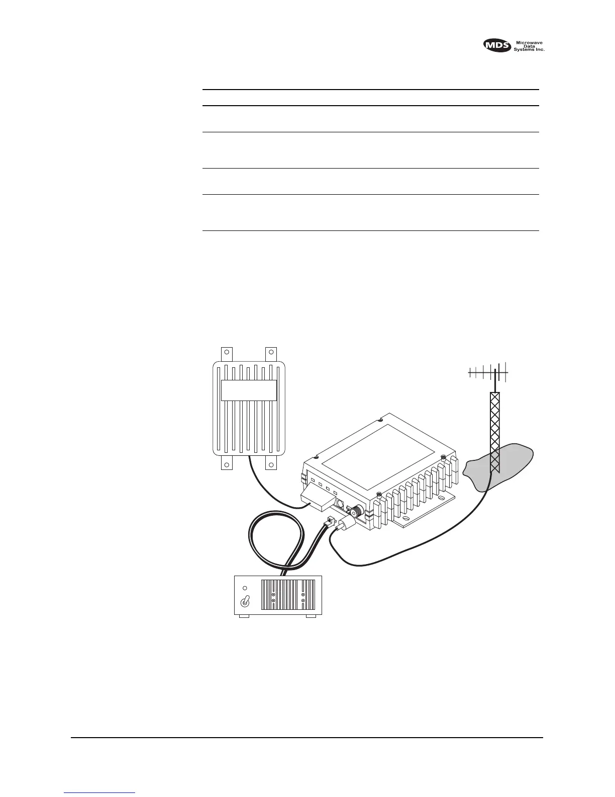
There are three main requirements for installing the transceiver—ade-
quate and stable primary power, a good antenna system, and the correct
interface between the transceiver and the data device. Figure 5 shows a
typical remote station arrangement.
Invisible place holder
Figure 5. Typical remote station arrangement
RJ-11 to DB-9 adapter Used to connect a PC to the radio’s
DIAGNOSTICS port
03-3246A01
RS-232 to RS-422
Converter Assembly
External adapter plug that converts the
radio’s DATA INTERFACE connector
to RS-422 compatible signaling.
03-2358A01
Radio Configuration
Software
Provides diagnostics of the transceiver
(Windows-based PC required.)
03-3156A01
Synchronous to
Asynchronous Data
Converter
Allows synchronous operation of the
x710 transceiver.
Contact MDS
Table 1. MDS x710B optional accessories
(Continued)
Accessory Description MDS P/N
13.8 VDC
POWER
CABLE
13.8 VDC
2.5 A (Minimum)
POWER SUPPLY
REMOTE TERMINAL
UNIT
ANTENNA SYSTEM
LOW-LOSS FEEDLINE
RADIO
TRANSCEIVER